Power transmitting apparatus

a technology of power transmission apparatus and transmission device, which is applied in the direction of friction clutch, mechanical actuator clutch, clutch, etc., can solve the problems of complex structure of power transmission apparatus and increase the malfunction of apparatus, so as to reduce the risk, surely and smoothly absorb the urging force, and simplify the structure of the power transmission apparatus

Inactive Publication Date: 2015-11-26
FCC KK
View PDF5 Cites 26 Cited by
  • Summary
  • Abstract
  • Description
  • Claims
  • Application Information

AI Technical Summary

Benefits of technology

[0017]In some embodiments, since the power transmitting apparatus comprises interlocking members (e.g., first member and second member) interlocking with the motion of the weight members from their radially inward positions to radially outward positions and movable toward a direction approaching to the pressure member; and elastic members interposed between the interlocking members and the pressure member and able to move the pressure member toward a direction for press-contacting the driving-side clutch discs and the driven-side clutch discs by urging the pressure member according to the movement of the interlocking members and also able to absorb the urging force of the pressure member applied to interlocking members when the actuating member is operated, it is possible to maintain the operability of the power transmitting apparatus during the manual cutting-off operation of power transmission, to simplify the structure of the power transmitting apparatus, and thus to reduce the risk of operational malfunction of the power transmitting apparatus.
[0018]In some embodiments, since the elastic members comprise springs interposed between the interlocking members and the pressure member, it is possible to surely and smoothly absorb the urging force of the pressure member applied to the interlocking members during operation of the actuating member.
[0019]In some embodiments, since the interlocking members comprises a first sheet member connected to the clutch housing and a second sheet member holding the elastic members, and a friction member is interposed between abutting surfaces of the first sheet member and the second sheet member, it is possible to smoothly perform sliding motion between the first and second sheet members during rotation of the first sheet member relative to the second sheet member and surely perform the integral rotation and movement of the first and second sheet members.
[0020]According to the present inventions of claim 4, since the power transmitting apparatus further comprises a holding device (urging device and stopper; abutting surface) for keeping a separated distance between the actuating member and the operating device and allowing the motion of the actuating member, it is possible to prevent the starting point of actuation of the actuating member from being differentiated by positions of the pressure member and thus to improve the operability of the clutch operation.
[0021]According to the present inventions of claim 5, since the power transmitting apparatus further comprises press-contact assisting cams formed by inclined cam surfaces formed on the clutch member and inclined cam surfaces formed on the pressure member which are arranged opposite each other and adapted to increase the press-contacting force between the driving-side clutch discs and the driven-side clutch discs when the rotational driving power inputted to the input member can be transmitted to the output member, it is possible to apply the press-contacting force to the driving-side clutch discs and the driven-side clutch discs in addition to the press-contacting force caused by movement of the weight members due to the centrifugal force and thus to achieve more smooth and sure press-contact of the driving-side clutch discs and the driven-side clutch discs.

Problems solved by technology

However, according to the power transmitting apparatus of the prior art, although it is possible to improve the operability of the power transmitting apparatus during cutting-off operation of the power transmission thanks to the fact that the position of the weight members (radially outward position) can be kept during cutting-off of the power transmission, since it requires two pressure plates such as the first and second pressure plates as movable members, there exists the problems that the structure of the power transmitting apparatus is complicated and malfunction of the apparatus would be increased.
There is concern that these problems would be caused when the cutting-off of power transmission is performed by a powered actuator such as an electric motor.

Method used


Image

  • Power transmitting apparatus
  • Power transmitting apparatus
  • Power transmitting apparatus

Examples


Embodiment Construction

[0039]Preferable embodiments of the present inventions will be hereinafter described with reference to the accompanying drawings.

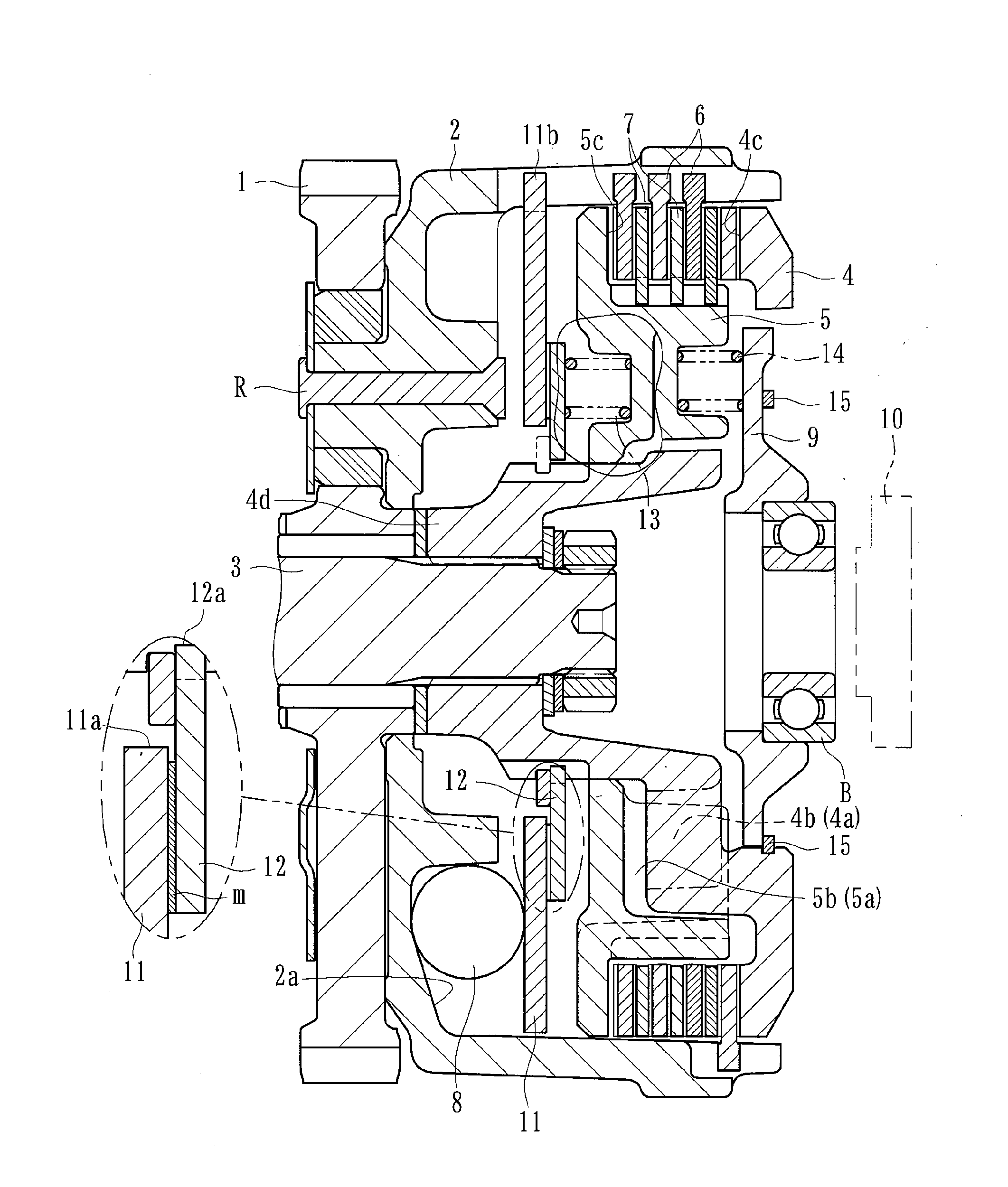
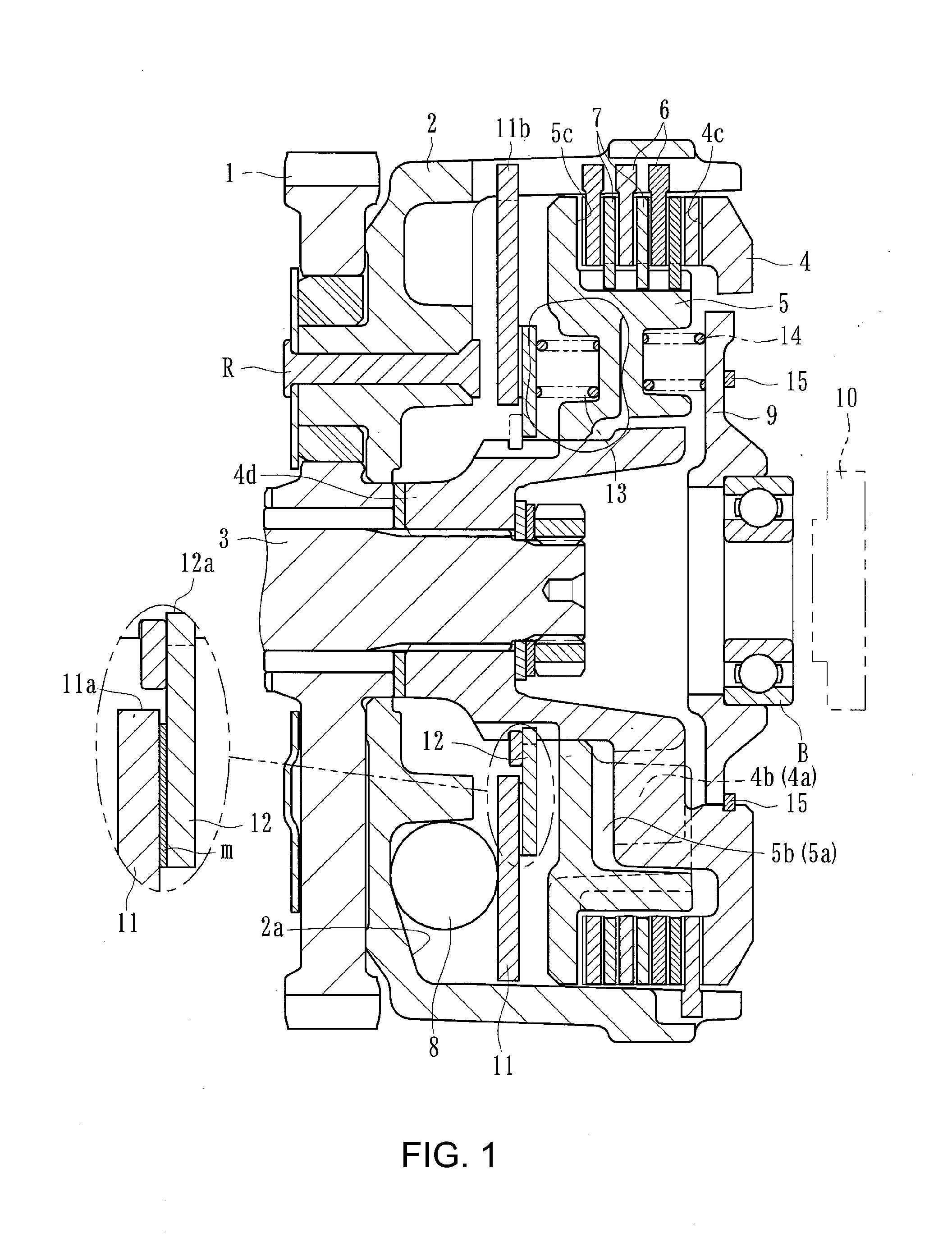
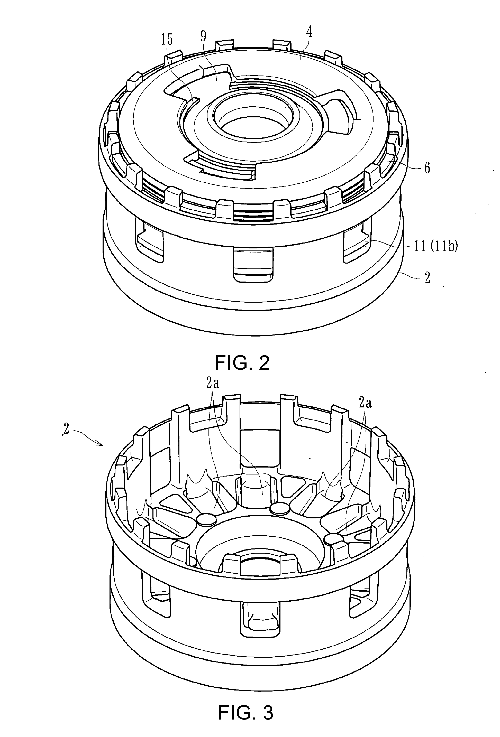
[0040]A power transmitting apparatus of a first embodiment of the present inventions can be mounted on a vehicle such as a motorcycle to arbitrarily transmit or cut-off the driving power of an engine to or from a transmission or driving wheel. As shown in FIGS. 1 and 2, the power transmitting apparatus mainly comprises a clutch housing 2 on which a gear 1 as an input member is mounted, a clutch member 4 connected to a shaft 3 as an output member, a pressure member 5 arranged at the left (e.g., in the frame of reference of FIG. 1) of the clutch member 4, a plurality of driving-side clutch discs 6 and a plurality of driven-side clutch discs 7, weight members 8 formed of hard balls rollable within the clutch housing 2 (e.g., one weight member 8 is shown in FIG. 1), a manually operable actuating member 9, a first sheet member 11 and a second sheet member 12 ac...


PUM


Abstract

A power transmitting apparatus for transmitting or cutting-off the rotational driving power inputted to an input member to or from an output member by press-contacting or releasing the press-contacting force between driving-side clutch discs and driven-side clutch discs, wherein the power transmitting apparatus comprises interlocking members (e.g., a first member and second member) interlocking with the motion of the weight members from their radially inward positions to radially outward positions and movable toward a direction approaching to the pressure member; and elastic members interposed between the interlocking members and the pressure member and able to move the pressure member toward a direction for press-contacting the driving-side clutch discs and the driven-side clutch discs by urging the pressure member according to the movement of the interlocking members and also able to absorb the urging force of the pressure member applied to interlocking members when the actuating member is operated.

Description

INCORPORATION BY REFERENCE TO ANY PRIORITY APPLICATIONS[0001]Any and all applications for which a foreign or domestic priority claim is identified in the Application Data Sheet as filed with the present application, or any corrections thereto, are hereby incorporated by reference under 37 CFR 1.57.BACKGROUND OF THE INVENTIONS[0002]1. Field of the Inventions[0003]The present inventions relate to a power transmitting apparatuses for arbitrarily transmitting or cutting-off the rotational driving power of an input member to or from an output member.[0004]2. Description of the Related Art[0005]In general, the power transmission apparatus for a motorcycle is intended to arbitrarily perform transmission of or cutting-off of the driving power of an engine to or from a transmission and a driving wheel and comprises an input member connected to an engine-side, an output member connected to a transmission and a driving wheel-side, a clutch member connected to the output member, and a pressure ...

Claims


Application Information

Patent Timeline
Patent Type & Authority Applications(United States)
IPC IPC(8): F16D43/12F16D13/56
CPCF16D43/12F16D2013/565F16D13/56
Inventor YOSHIMOTO, KATSUCHEN, HAN HIONGAONO, KAORUMURAI, MASATAKA
Owner FCC KK
Why Eureka
Try Eureka