Variable magnetic flux-type rotary electric machine

a rotary electric machine and magnetic flux technology, applied in the direction of dynamo-electric machines, magnetic circuit rotating parts, magnetic circuit shape/form/construction, etc., can solve the problems of high energy loss, design and use restrictions, etc., to inhibit the amount of magnetic flux leakage, and generate maximum torque

Active Publication Date: 2015-11-26
WISCONSIN ALUMNI RES FOUND +1
View PDF8 Cites 12 Cited by
  • Summary
  • Abstract
  • Description
  • Claims
  • Application Information

AI Technical Summary

Benefits of technology

[0007]With the rotary electric machine of the present disclosure, loss during low load, loss during high-speed rotation, and ohmic loss can be inhibited by forming magnetic flux bypass paths that can inhibit the amount of magnetic flux leakage due to the stator armature action between adjacent magnetic poles. In addition, generation of maximum torque during high load can be achieved by inhibiting magnetic flux leakage due to the armature action. As a result, consumption of electricity during travel mode can be grea

Problems solved by technology

Control is thus difficult, and because magnets with small coercive field strengths have been used in order to control magnetic forces, it has been difficult to avoid demagnetization due t

Method used


Image

  • Variable magnetic flux-type rotary electric machine
  • Variable magnetic flux-type rotary electric machine
  • Variable magnetic flux-type rotary electric machine

Examples


first embodiment

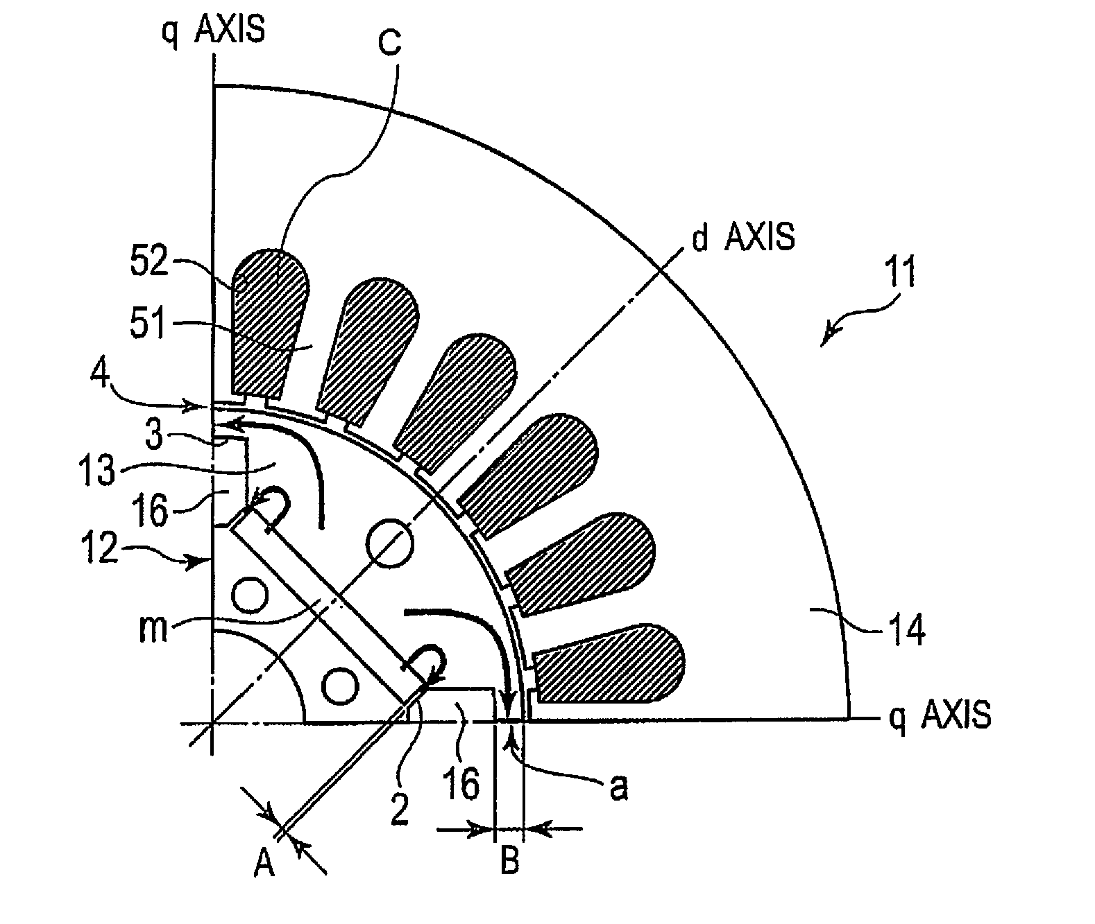
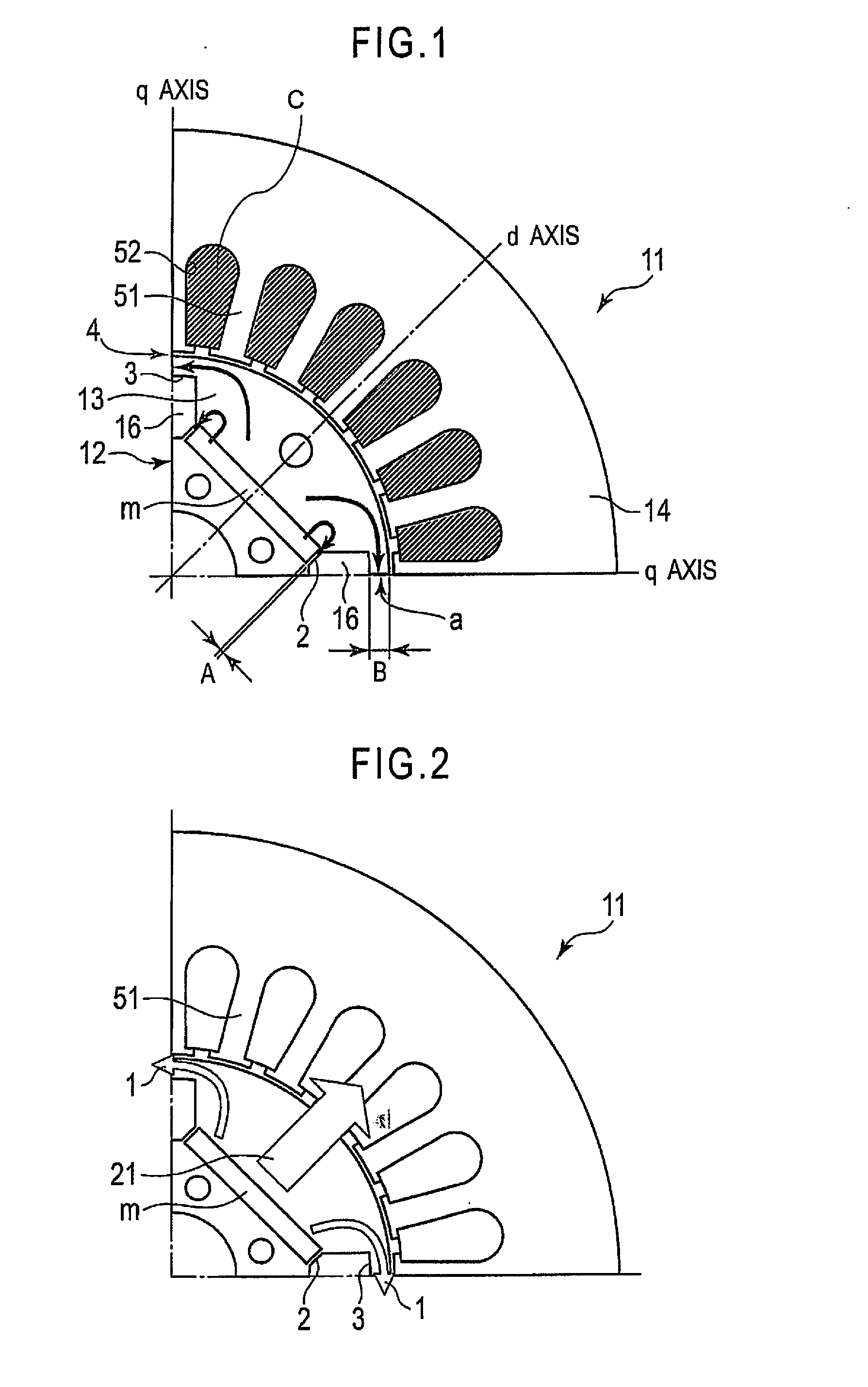
[0025]FIG. 1 is a diagram showing the configuration of a rotary electric machine pertaining to a first embodiment. A portion that constitutes one-fourth of the entire configuration is shown. Each other one-fourth of the remaining three-fourth of the entire configuration of the rotary electric machine repeats the illustrated one-quarter in a continuous repeating manner. As shown in FIG. 1, this rotary electric machine has a stator 11 that is formed in the shape of a ring, and a rotor 12 that is formed in the shape of a circle that is concentric with the stator 11 to form an electric motor or generator.

[0026]The stator 11 has a stator core 14 and a plurality of (e.g., 24) teeth 51 that protrude inwards from the stator core 14. The spaces between adjacent teeth 51 are regarded as slots 52. A stator coil C is wound on the teeth 51. The stator core 14 is formed, for example, from laminated iron sheets.

[0027]The rotor 12 has a rotor core 13, where the rotor core 13 is formed in the shape ...

second embodiment

[0060]A second embodiment is described below. FIG. 9 is a diagram showing the configuration of the rotary electric machine of the second embodiment. In FIG. 9, only one-fourth of the entire rotary electric machine is shown. Each other one-fourth of the remaining three-fourth of the entire configuration of the rotary electric machine repeats the illustrated one-quarter in a continuous repeating manner. For the sake of simplicity, the same reference numbers of the first embodiment will be used to describe the second embodiment. As shown in FIG. 9, as with the first embodiment described above, the rotary electric machine of the second embodiment has the annular stator 11 and the rotor 12 concentrically arranged with the air gap 4 serving as a gap portion between the stator 11 and the rotor 12. The rotor 12 has a rotor core 13.

[0061]On the circumferential edge part of the stator core 13 opposite the stator 11, four permanent magnets m (specifically, a quadrupole structure) are provided ...

third embodiment

[0067]A third embodiment is described below. FIG. 11 is a diagram showing the configuration of the rotary electric machine according to a third embodiment. FIG. 11, as with the first and second embodiments, shows only one-fourth of the entire rotary electric machine. Each other one-fourth of the remaining three-fourth of the entire configuration of the rotary electric machine repeats the illustrated one-quarter in a continuous repeating manner. For the sake of simplicity, the same reference numbers of the first embodiment will be used to describe the third embodiment. As shown in FIG. 11, as with the first and second embodiments described above, the rotary electric machine of the second embodiment has the annular stator 11 and the rotor 12 concentrically arranged with the air gap 4 serving as a gap portion between the stator 11 and the rotor 12. The rotor 12 includes the rotor core 13.

[0068]On the circumferential edge part of the stator core 13 opposite the stator 11, four permanent...


PUM


Abstract

A variable magnetic flux-type rotary electric machine includes a stator and a rotor. The stator includes a stator coil wound on teeth. The rotor defines an air gap between the rotor and the stator. The rotor has at least one permanent magnet arranged in the d-axis magnetic path. The stator and the rotor are arranged relative to the permanent magnet to set a characteristic of d(Kt(I))/dI≧0 in a range of at or below magnetic saturation of a core material of at least one of the stator and the rotor, where KT represents a torque constant, and I represents an applied current, and a function of KT with respect to I is represented by KT=Kt(I) for a torque Tr acting on the rotor that is represented by Tr=KT×I.

Description

BACKGROUND[0001]1. Field of the Invention[0002]The present invention generally relates to a variable magnetic flux-type rotary electric machine.[0003]2. Background Information[0004]A rotary electric machine in which the armature magnetic flux linkage is varied has been disclosed in Japanese Laid-Open Patent Application No. 2006-280195 and the like (e.g., Japanese Laid-Open Patent No. 2006-280195). However, with the rotary electric machine disclosed in Japanese Laid-Open Patent Application No. 2006-280195, it has been necessary to control the magnetized state of the magnets. Control is thus difficult, and because magnets with small coercive field strengths have been used in order to control magnetic forces, it has been difficult to avoid demagnetization due to armature counteraction, resulting in restrictions on design and uses. In addition, there have been problems with high energy loss due to the flow of magnetization / demagnetization current.SUMMARY[0005]One object presented in thi...

Claims


Application Information

Patent Timeline
IPC IPC(8): H02K1/27
CPCH02K1/276H02K1/2766H02K1/2773
Inventor KATO, TAKASHILORENZ, ROBERTLIMSUWAN, NATEE
Owner WISCONSIN ALUMNI RES FOUND
Why Eureka
Try Eureka