Knee joint prosthesis

Inactive Publication Date: 2015-12-03
FILLAUER EURO AB +1
View PDF22 Cites 5 Cited by
  • Summary
  • Abstract
  • Description
  • Claims
  • Application Information

AI Technical Summary

Benefits of technology

[0027]Another important advantage of the present invention is that the prosthetic knee fits amputees with long residual limbs, such as AK amputees—a method that is preferred today. Another important advantage is that the present invention is also compatible with a lower limb prosthesis using a low weight prosthesis foot. A problem for knee joint prostheses found in prior art is that a sufficient pendulum motion is not achieved when the pendulum, for instance a foot, does not have a sufficient weight. The absence of the need of a pendulum motion makes the present knee joint prosthesis superior to prior art.
[0028]The present invention is compatible with the use of low weight prosthesis and at the same time has a natural-looking appearance and a function that mimics the natural movements of an artificial leg. These are some of the problems of the prior art solved by the present invention.
[0029]The advantages with a knee joint prosthesis according to the present invention are many. Firstly the support surrounding the knee joint prosthesis is much lighter compared to those found on the market today, making movements easier for the amputee. Secondly, the prosthesis may be fitted more exact in relation to the corresponding place for the natural knee, something that is not possible today. The knee joint prosthesis center

Problems solved by technology

A disadvantage with current methods for providing a prosthesis is that knee joints used today are relatively large, which can be inconvenient for the amputee in many ways, for example by distorting posture or hindering movements.
One problem with this design is that the socket is always a little bit wider than the knee joint prosthesis and will be placed proximal to the knee joint prosthesis.
This means that the knee joint prosthesis ends up in the wrong place if the residual limb/amputation stump is long.
A knee joint prosthesis that is in the wrong place looks strange and it is difficult to make it work in an anatomically correct manner.
If the lower limb and/or foot is too light, the pendulum will not gain enough energy to sufficiently brake the motion.
One of the problems today is that if the lower limb prosthesis and/or prosthesis foot have too low weight they cannot properly function as a pendulum providing sufficient kinematic energy to dampen the movement.
In addition, friction from clothes and from the cosmetics surrounding the prosthesis further impedes movement of the pendulum, causing the person to need even more inertia.
Doing this in a slow and controlled manner can be difficult for an amputee using a prosthesis, and is impossible to do with an above the knee, AK, prosthesis that only dampens the knee joint.
It can also be difficult to walk at a slow pace, in a hill or in stairs.
However, the microprocessor controlled knee joints known today are relatively heavy compared to natural joints and do not take into account whether the amputation stump is long or short.
Depending on the length of the amputation stump the knee joints may have significant height differences, which may bring unnec

Method used


Image

  • Knee joint prosthesis
  • Knee joint prosthesis
  • Knee joint prosthesis

Examples


Example

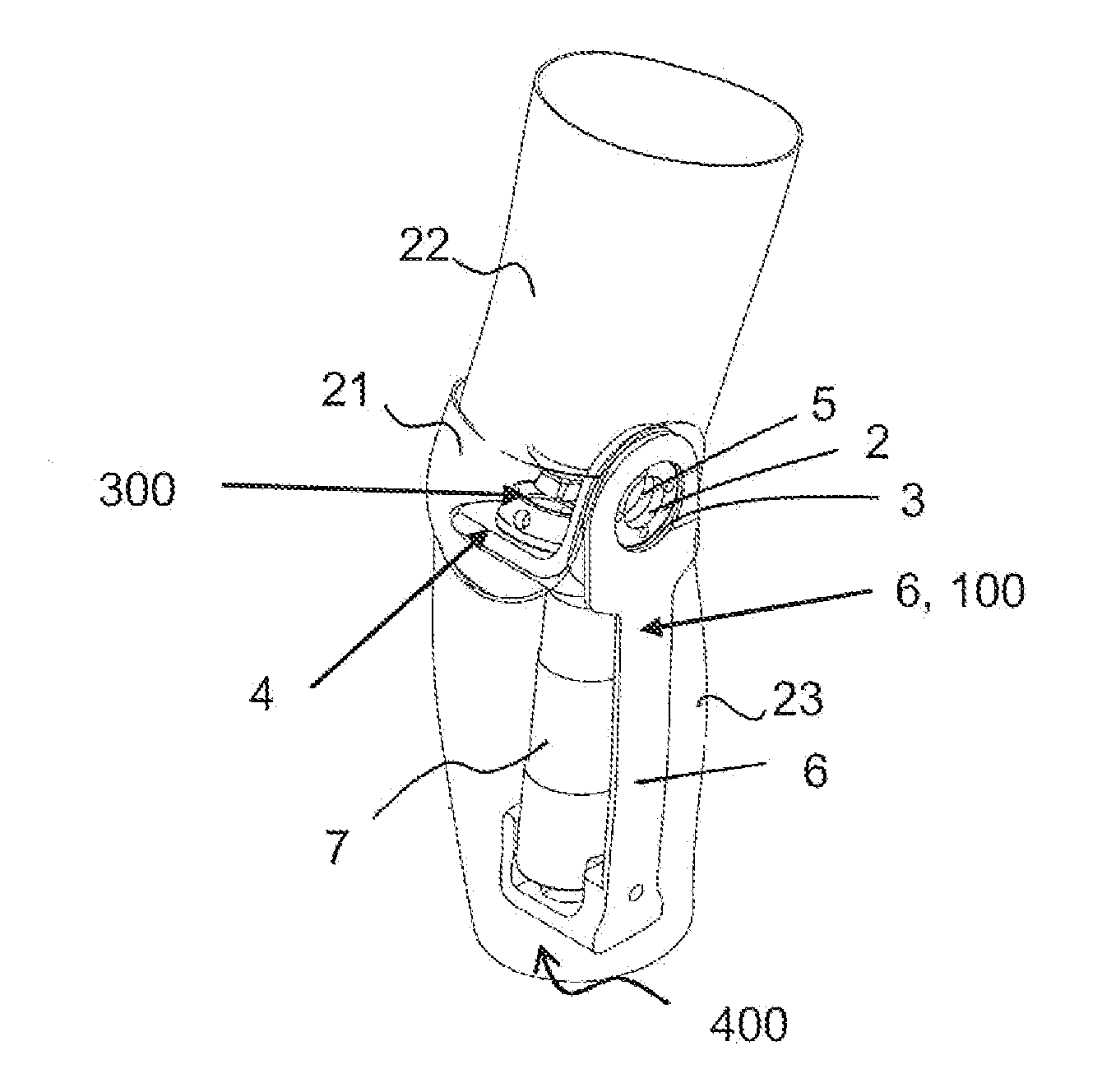
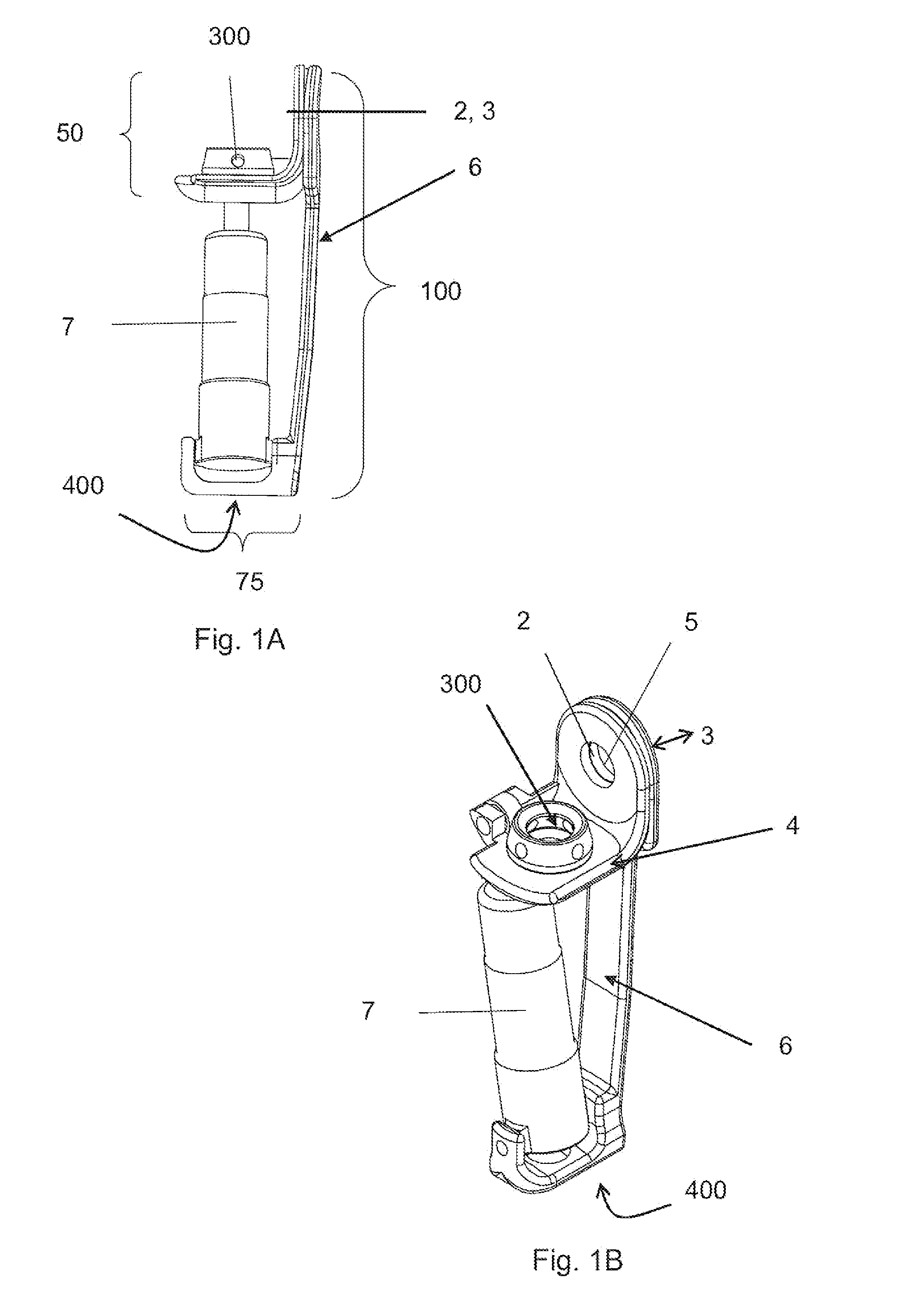
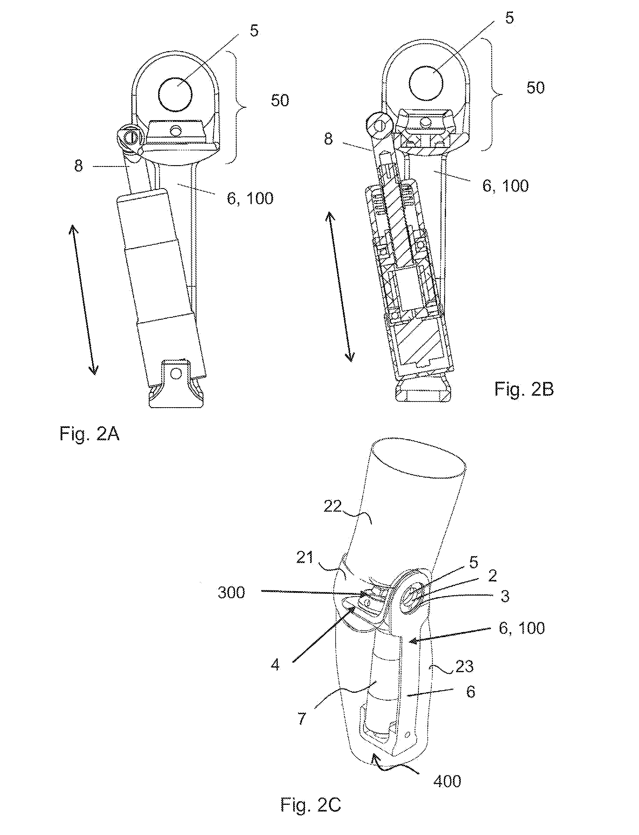
[0053]A first embodiment of the actuator 7 is shown in FIG. 3b and is an actuator comprising a shaft 8 that moves in the axial direction of the shaft 8 and a housing 9. The housing 9 protects the electric motor 10. The electric motor 10 turns a nut 11 and the shaft 8 moves in the axial direction, and then changes the angular velocity of the artificial knee joint. A thread 12 on the shaft 8 has a high pitch. If the shaft 8 drives back and forth, the shaft 8 will rotate the nut 11. If the nut 11 is rotating without help of the motor, for instance when a user moves the leg without help from the power source, it will spin the electric motor that will produce electric energy when the shaft 8 is moved. In embodiments incorporating a chargeable power source, this electric energy can be used to charge the power source.

Example

[0054]FIG. 3c shows a sectional view of a second embodiment of the actuator 7 comprising a linear motor 17. The actuator 7 can also for example comprise an axle 16 that is included in the linear motor 17, which is made up of solenoids 18 and magnets 19 that move the axle in a linear direction, and if the axle is moved linearly it induces electric energy in the linear motor 17.

Example

[0055]FIG. 3d shows a third embodiment of the actuator 7 comprising an electric motor that rotates a ball screw nut 13 and moves a ball screw shaft 8 linearly, or the ball screw is moved linearly and the motor generates energy. The nut can also for example be a ball nut to reduce friction between a thread 14 and a nut. The coupling between the nut and the motor can also for example be a free needle hub bearing coupling 15. However, the invention is not limited to a certain type of drive motor, for example a belt motor drive or a hollow shaft motor may also be used.

[0056]FIG. 4 shows a flow chart describing the operation of the knee joint of the present invention using an electric control system. The microprocessor measures all sensors at least at 1 kHz and decides if the knee shall flex or extend as well as how fast the motions should be. The microprocessor then controls the motor in the actuator to work as a motor consuming energy or generating energy depending on the angular veloc...


PUM


Abstract

The present invention relates to a knee joint for use in a lower limb prosthesis. The knee joint comprise an upper portion for connecting a custom socket and a proximal attachment, and a support comprising connecting means in its lower part for connecting a prosthetic limb. The support has at least one attachment arm on the medial or the lateral side of the knee joint prosthesis. An actuator is connected between a proximal attachment and the support and is adapted to pivot the upper portion relatively to the support. The actuator comprises a motor directly operatively connected to an axial displaceable shaft capable of changing angular velocity of the knee joint. An external control device can be used to control the knee joint.

Description

TECHNICAL FIELD[0001]The present invention relates to the field of knee joint prostheses.BACKGROUND ART[0002]When a person is amputated above the knee a lower limb prosthesis comprising a prosthesis knee joint is usually needed. When the lower limb prosthesis is manufactured a casting of the amputation stump is made, serving as a template for the custom socket, i.e. the part that is attached to the amputation stump.[0003]Today the amputation stump is kept as long as possible when a limb is amputated. The reason for this is that it is easier to control the prosthetic limb with a longer residual limb. A longer residual limb can withstand a higher load from the prosthetic limb than a shorter one. It is important that the amputation stump is as long as possible because then the load will be distributed on a larger body surface area, and that will reduce the pressure and shear forces exerted on the amputation stump.[0004]More and more amputees are amputated through the knee through knee ...

Claims


Application Information

Patent Timeline
IPC IPC(8): A61F2/64A61F2/68
CPCA61F2/64A61F2/68A61F2002/607A61F2002/7645A61F2002/701A61F2002/764A61F2002/768A61F2002/707A61F2002/7625A61F2002/7635A61F2/76A61F2002/7695A61F2/70
Inventor HELLBERG, KENNETRANDSTROM, ALEXANDER
Owner FILLAUER EURO AB
Why Eureka
Try Eureka