
Reverse osmosis system with valves for controlling a work exchanger sysyem

a technology of work exchanger and reverse osmosis system, which is applied in the direction of water treatment parameter control, cartridge filter, water/sludge/sewage treatment, etc., can solve the problems of excessive wear on sealing surfaces, rotary valve device of tonner not hydraulically balanced, and energy is the largest operating cost of any reverse osmosis facility

Inactive Publication Date: 2015-12-03
IDE TECHNOLOGIES
View PDF3 Cites 2 Cited by
  • Summary
  • Abstract
  • Description
  • Claims
  • Application Information

AI Technical Summary

Benefits of technology

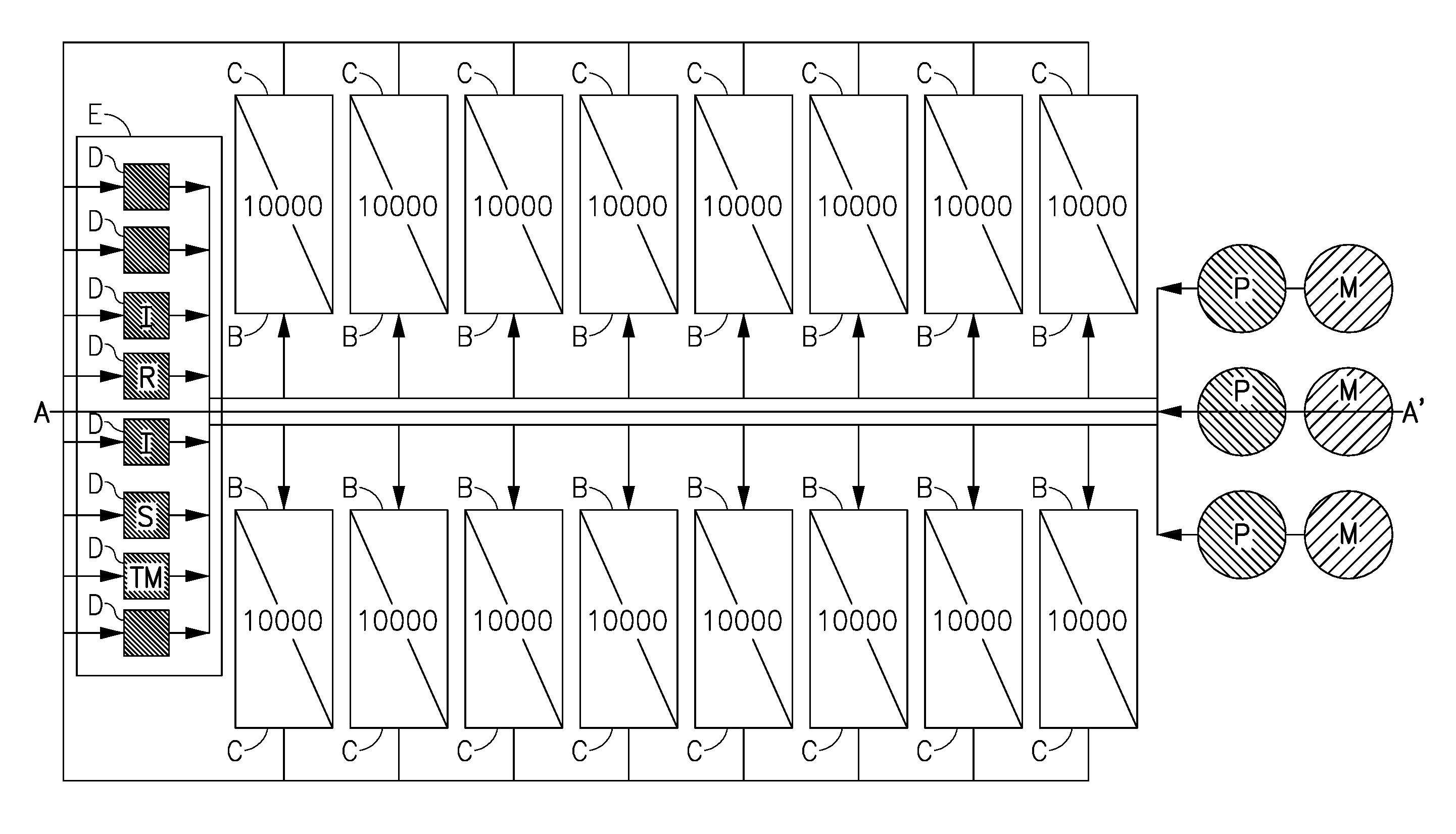
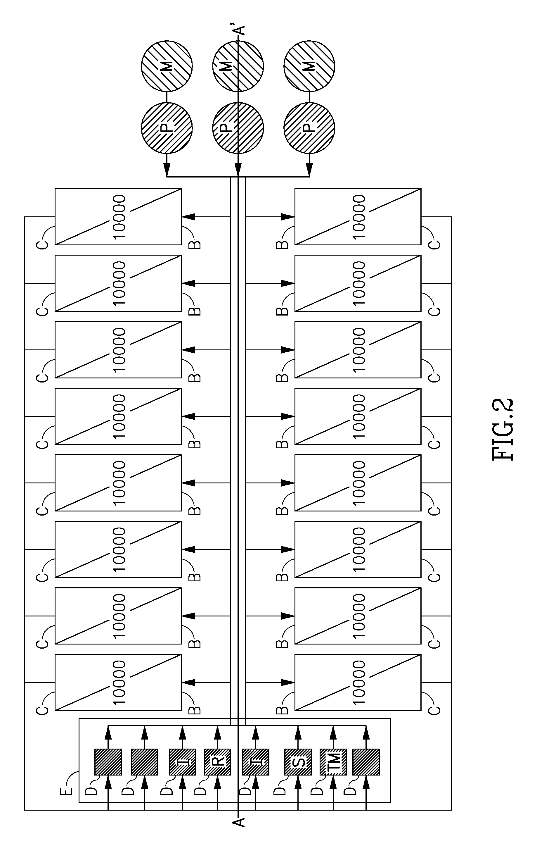
This patent is about a work exchanger system that has three work exchange chambers. Each chamber is connected to a valve that has a bypass channel to equalize pressure on both sides of the valve. The system also has a controller that controls each valve to maintain a constant and continuous flow of high pressure brine into the system. The technical effect of this invention is to provide a more efficient and effective work exchanger system that ensures a continuous and stable operation.

Problems solved by technology

Energy is the largest operating cost in any reverse osmosis facility.
However, the rotary valve device of Tonner is not hydraulically balanced and this is a major disadvantage.
Lack of hydraulic balance in the Tonner device causes excessive wear on the sealing surfaces due to side loads exerted on the central spool piece.
Once the power stroke is completed, the spool turns and the cylinder pressure is decreased and equalized with the low pressure feed while exposing the spool to unbalanced side loads.
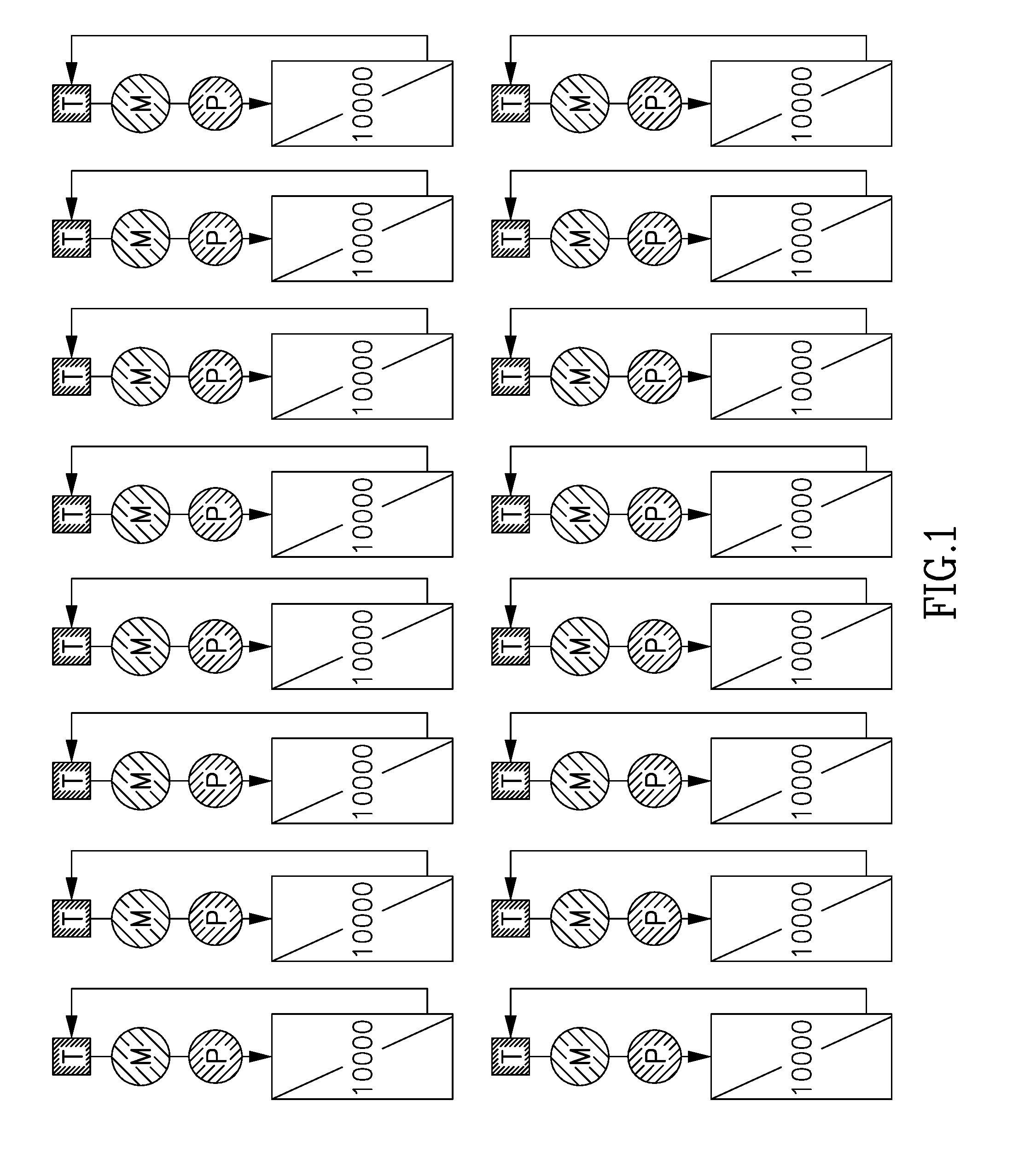
A further major disadvantage of the Tonner device relates to the fact that it does not have, in its operation, an “overlap period” in which high pressure brine may be consumed and flow continuously by and into each work exchanger cylinder.
This is a critical problem because the brine flow from the membrane in a reverse osmosis system must never be restricted.
However, expanding reverse osmosis plants into mega-plants challenges existing reverse osmosis train configuration as rival factors should be considered and optimized.

Method used


Image

  • Reverse osmosis system with valves for controlling a work exchanger sysyem
  • Reverse osmosis system with valves for controlling a work exchanger sysyem
  • Reverse osmosis system with valves for controlling a work exchanger sysyem

Examples


Embodiment Construction

[0019]With specific reference now to the drawings in detail, it is stressed that the particulars shown are by way of example and for purposes of illustrative discussion of the preferred embodiments of the present invention only, and are presented in the cause of providing what is believed to be the most useful and readily understood description of the principles and conceptual aspects of the invention. In this regard, no attempt is made to show structural details of the invention in more detail than is necessary for a fundamental understanding of the invention, the description taken with the drawings making apparent to those skilled in the art how the several forms of the invention may be embodied in practice.

[0020]Before explaining at least one embodiment of the invention in detail, it is to be understood that the invention is not limited in its application to the details of construction and the arrangement of the components set forth in the following description or illustrated in ...


PUM

PropertyMeasurementUnit
dwelling timeaaaaaaaaaa
delay timeaaaaaaaaaa

Abstract

A system and method for the structure and operation of a work exchanger system in a reverse osmosis plant is disclosed. The work exchanger system is characterized by a an array of multiple work exchanger chambers each being individually controlled and operated to a meet an aggregate need of pressure recovery by the entire system. Each work exchanger chamber is characterized by at least one valve having a bypass system which is configured to equalize pressure on both sides of the valve. Such an equalizing process's delays are monitored and controlled by the central systems' controlling system to create no restrictions to reject high pressure brine flow in a reverse osmosis system at any given time.

Description

TECHNICAL FIELD[0001]The present invention relates to a multiple valves device, for directing the flow of fluid in a work exchanger system and more particularly, to an array of multiple work exchangers, operating in a controlled dwelling time to synchronize pistons' power strokes and exhaust strokes in order to continuously consume, recover and direct high pressure reject stream of a reverse osmosis system.BACKGROUND[0002]As demand for potable water grows and energy costs increase, the energy efficient and scalable design of the seawater reverse osmosis process, makes it the preferred desalination process in many regions around the world. Energy is the largest operating cost in any reverse osmosis facility. Energy recovery devices are critical to maintain the cost effectiveness of reverse osmosis facilities. Efficiency, complexity, reliability, maintainability, operability and costs of the energy recovery system play a critical role in the ability to recover pressure energy from rej...

Claims


Application Information

Patent Timeline
Patent Type & Authority Applications(United States)
IPC IPC(8): B01D61/02C02F1/44B01D61/12
CPCB01D61/025B01D61/12C02F2209/03C02F2103/08C02F1/441B01D61/06B01D2311/04B01D2311/14B01D2313/18B01D2313/246B01D2311/08B01D2311/165B01D61/02
Inventor LEVITIN, VITALYLIBERMAN, BORIS
Owner IDE TECHNOLOGIES
Learn More