


Quick Research
Generate reliable direction feasibility study reports for your R&D in just a few steps.

Technical Q&A
Discover and master advanced knowledge NOW. Basics, ideas, possibilities, all at once.

Find Solutions
As an expert in R&D theories, this can generate solutions to your technical problems instantly.

Evaluate Feasibility
Analyze your overall solution with one click, know your potential R&D risks in advance.

Monitor Landscape
Get weekly tech updates, stay abreast of the latest tech innovations and key insights.
Mold structure, transfer molding apparatus, and transfer molding method
a transfer molding and mold technology, applied in the direction of dough shaping, manufacturing tools, applications, etc., can solve the problems of low heat exchange efficiency, low workability in replacing the transfer plate, and burns of the worker's mold at high temperature, and achieve the effect of easy replacemen
- Summary
- Abstract
- Description
- Claims
- Application Information
AI Technical Summary
Benefits of technology
Problems solved by technology
Method used
Image

Examples
first embodiment
Configuration
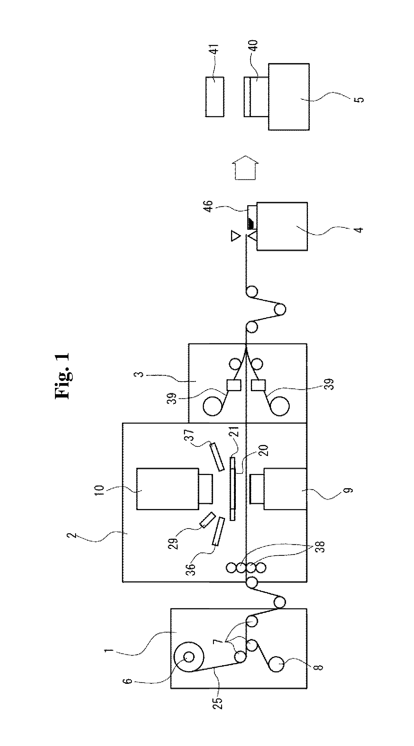
[0055]FIG. 1 is a schematic view of a light guide plate manufacturing system according to a first embodiment. The light guide plate manufacturing system includes a material feeder 1, a transfer molding apparatus 2, a film applicator 3, a cutter 4, and a shaping apparatus 5.
[0056]The material feeder 1 rewinds a resin sheet 25 from a main roller 6 and feeds the sheet to the transfer molding apparatus 2. The resin sheet 25 is transported by a plurality of rollers 7 arranged midway to the transfer molding apparatus 2. Immediately after passing the second one of the rollers 7, a protective sheet bonded to the resin sheet 25 is separated and wound by a winding roller 8. The resin sheet 25 is made of polycarbonate (with a melting point of about 240° C. and a glass-transition temperature of about 150° C.).
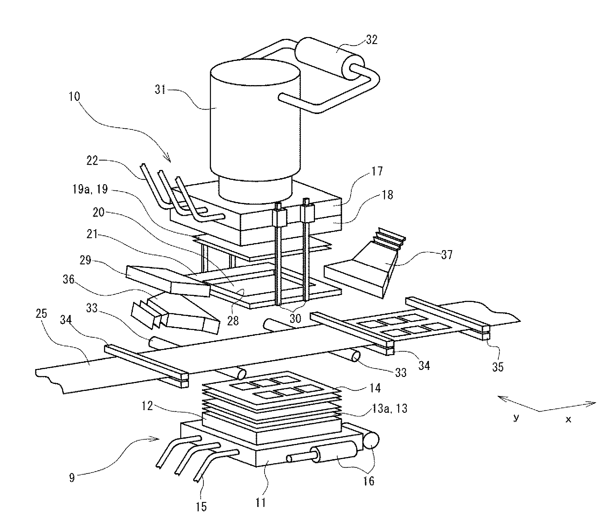
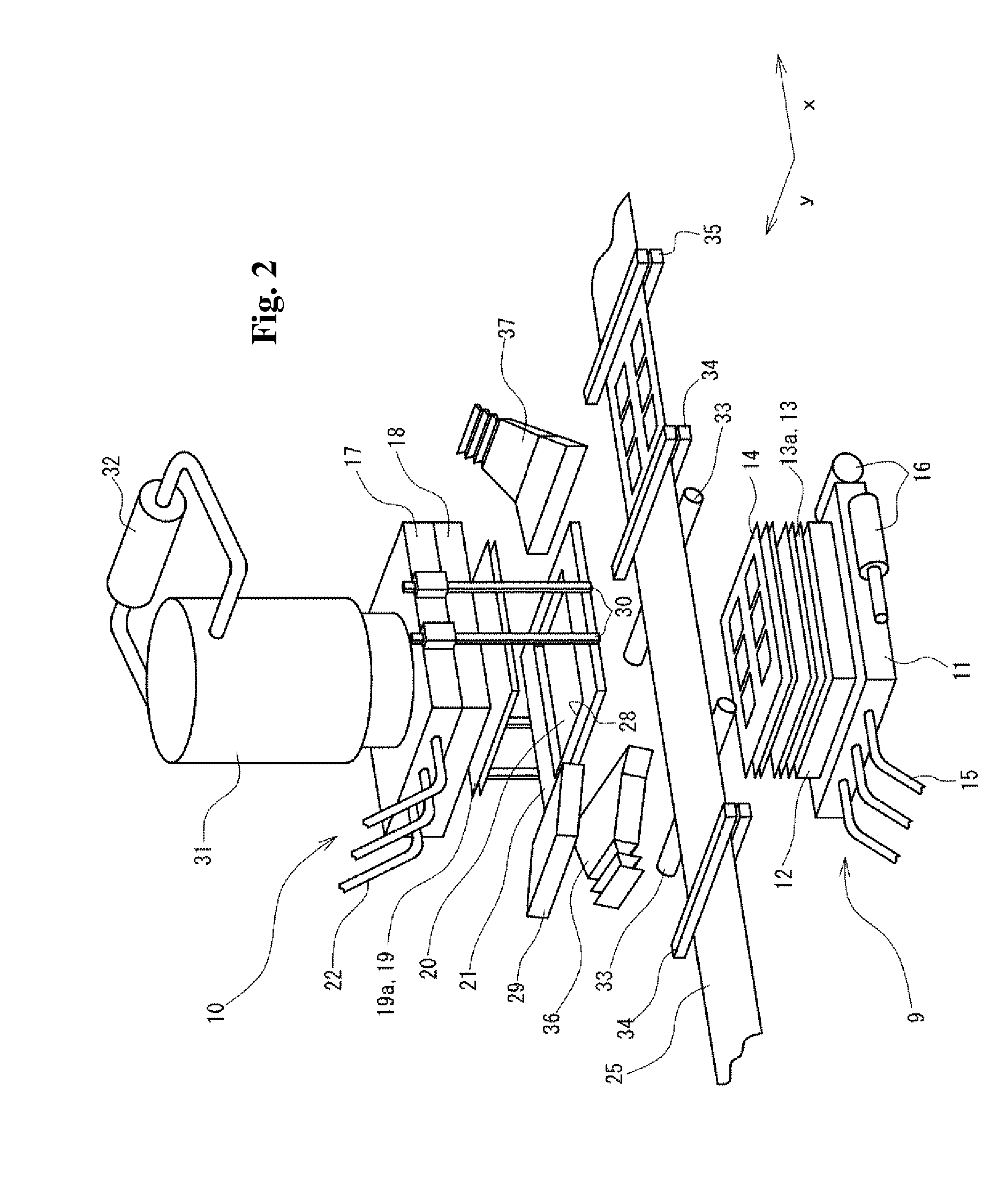
[0057]As shown in FIG. 2, the transfer molding apparatus 2 includes a lower mold 9 and an upper mold 10. The lower mold 9 includes a lower mold support 11, on the upper surfac...
second embodiment
[0105]The system shown in FIG. 6 uses a direct cooling method for cooling an upper mold transfer plate 20 by direct contact with a cooling plate 50, instead of using the air cooling method of cooling the upper mold transfer plate 20 with air blown from the intake duct 36.
[0106]The cooling plate 50 can reciprocate between a transfer area defined in the molds and a non-transfer area defined outside the molds by a horizontal moving mechanism (not shown). An auxiliary heat insulating plate 51 is formed integrally with the upper surface of the cooling plate 50. When an upper transfer plate is retained on the retainer plate 21, the lower surface of the upper transfer plate can come in contact with the upper surface of the resin sheet 25, and the upper surface of the upper transfer plate can come in contact with the lower surface of the cooling plate 50. The cooling plate 50 is water-cooling, and uses a fluid flowing through a pipe (not shown) to maintain the surface temperature to a const...
third embodiment
[0116]The system according to a third embodiment includes a cooling mechanism that cools the resin sheet 25 both from above and below, or specifically cools the upper surface of the upper mold transfer plate 20 and the lower surface of the lower mold transfer plate 14 as shown in FIGS. 9(a) to 10(c).
[0117]Whereas the system of the second embodiment includes the cooling plate 50 formed integrally with the auxiliary heat insulating plate 51 on its upper surface, the system of the third embodiment includes not only a first cooling plate 52 formed integrally with an auxiliary heat insulating plate 53 on its upper surface, which corresponds to the cooling plate 50, but also a second cooling plate 54 formed integrally with an auxiliary heat insulating plate 55 on its lower surface. The lower mold excluding the lower mold transfer plate 14 is entirely movable to a position at which the lower mold is retracted in the horizontal direction. The first cooling plate 52 and the second cooling pl...
PUM
| Property | Measurement | Unit |
|---|---|---|
| Temperature | aaaaa | aaaaa |
| Structure | aaaaa | aaaaa |
| Transition temperature | aaaaa | aaaaa |
Abstract
Description
Claims
Application Information
 - R&D Engineer
- R&D Manager
- IP Professional
- Industry Leading Data Capabilities
- Powerful AI technology
- Patent DNA Extraction
Browse by: Latest US Patents, China's latest patents, Technical Efficacy Thesaurus, Application Domain, Technology Topic, Popular Technical Reports.
© 2024 PatSnap. All rights reserved.Legal|Privacy policy|Modern Slavery Act Transparency Statement|Sitemap|About US| Contact US: help@patsnap.com