Methods for Obtaining Hydrophilic Fluoropolymers

a fluoropolymer and hydrophilic technology, applied in the field of thermoplastic material processing, can solve the problems of long processing time, limited use of polytetrafluoroethylene (ptfe) in various applications, and difficulty in adhesion

Inactive Publication Date: 2015-12-03
UNIV GENT
View PDF2 Cites 265 Cited by
  • Summary
  • Abstract
  • Description
  • Claims
  • Application Information

AI Technical Summary

Benefits of technology

[0008]It is an object of embodiments of the present invention to provide good methods for rendering fluoropolymers hydrophilic. It was surprisingly found that methods avoiding chemical hazards allow rendering fluoropolymer hydrophilic to water contact angles below 30°, advantageously a contact angle below 20°, more advantageously a contact angle below 10°.
[0009]It is an advantage of embodiments according to the present invention that methods can be provided for tuning the hydrophilic behavior of fluoropolymer, e.g. in a range down to contact angle below at least 30°, advantageously below 25°, more advantageously a contact angle in a range down to 20°, more advantageously a contact angle down to 10°.
[0010]It is an advantage of embodiments according to the present invention that the hydrophilic behavior of fluoropolymer substrates can be tuned, in the sense that the fluoropolymer substrates can be rendered hydrophilic in a selective manner, e.g. at one side of the substrate or only at a selected area of the substrate.

Problems solved by technology
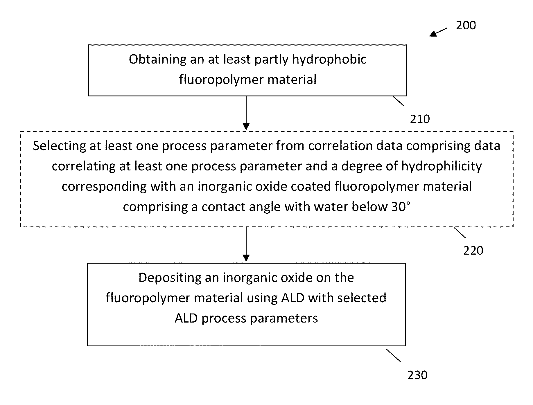
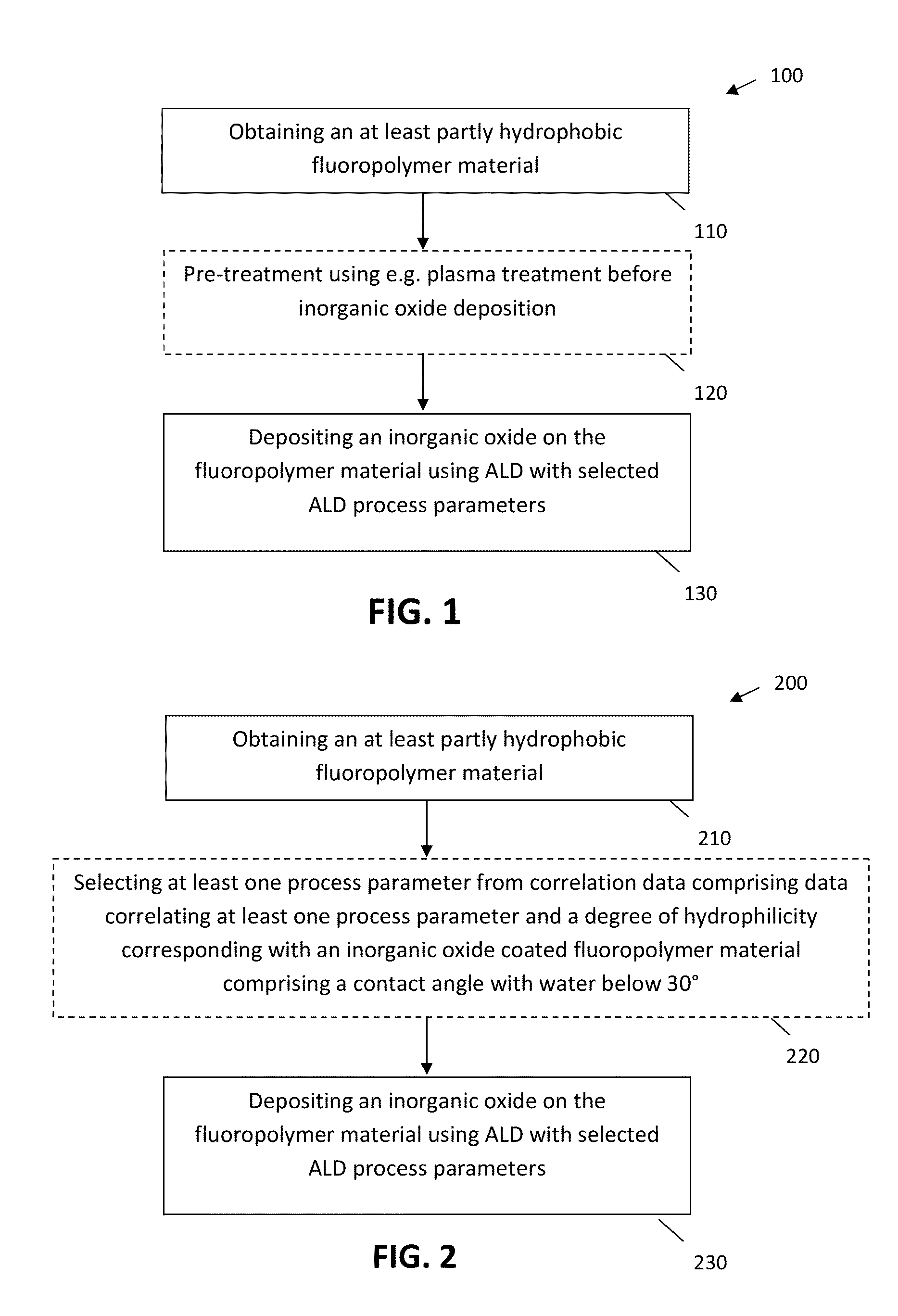
Nevertheless, the use of polytetrafluoroethylene (PTFE) is restricted in various applications due to its chemical inertness and hydrophobic nature.
For example, native porous PTFE is not suitable for water filtration membrane or leads to adhesion difficulties when used with other substrates such as metals, polymers and ceramic materials.
In these known methods, hydrophilic PTFE is achieved by wet chemical methods which involve hazardous organic solvents, whereby long processing time is required to get rid of these solvents.
Thus, these methods are time consuming and also involve chemical hazards.
Nevertheless, attempts to render native hydrophobic PTFE hydrophilic by applying oxygen plasma treatment did not succeed.
In the study of Kemell et al. increasing the number of cycles thereby does not seem to allow to further reduce the water contact angle.
Furthermore, it was shown in Kemell et al. that the deposited thin films on PTFE did not pass the Scotch tape test, indicating poor adhesion properties of the deposited films.

Method used


Image

  • Methods for Obtaining Hydrophilic Fluoropolymers
  • Methods for Obtaining Hydrophilic Fluoropolymers
  • Methods for Obtaining Hydrophilic Fluoropolymers

Examples


experiment 1

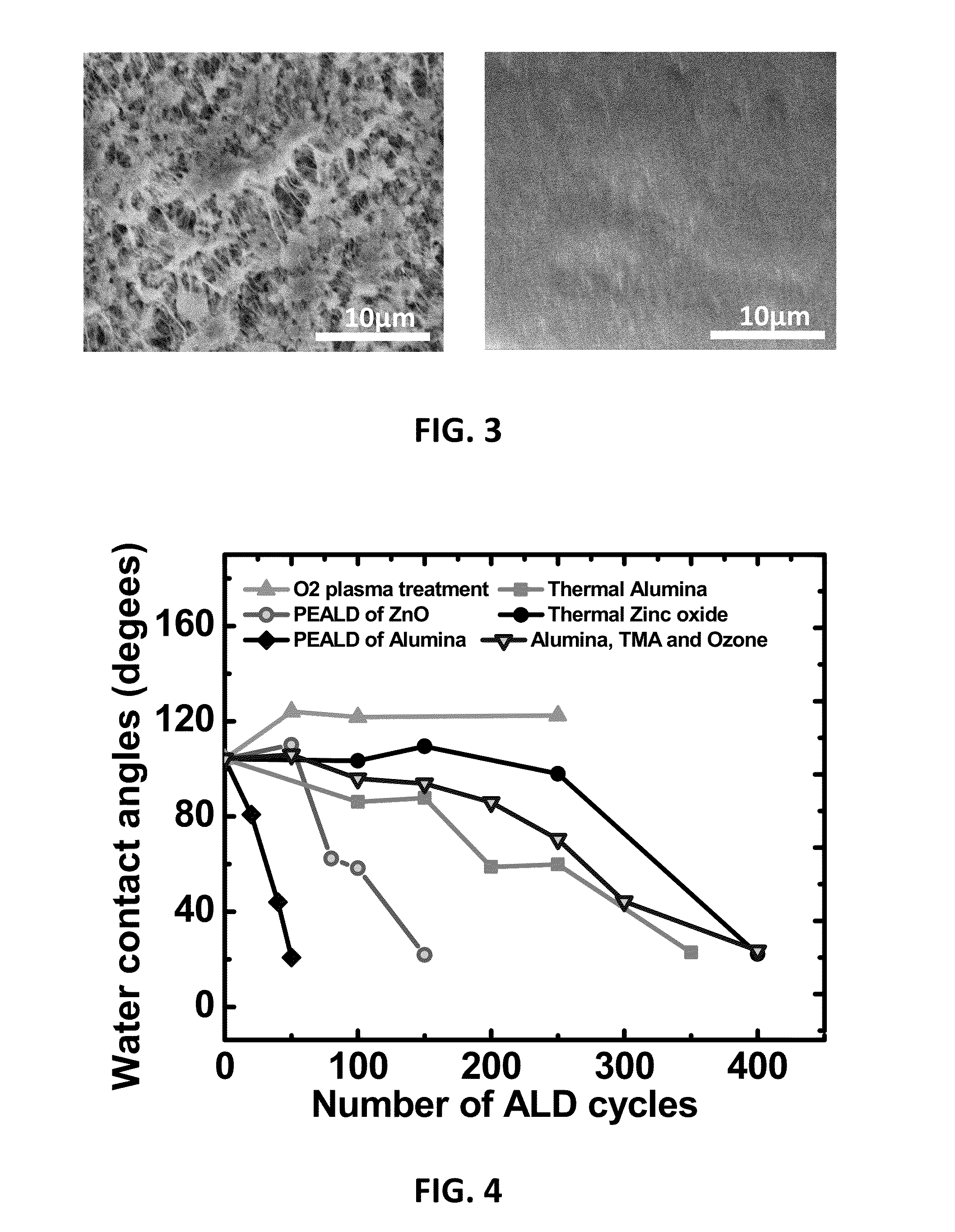
[0079]Aluminum oxide was deposited using thermal atomic layer deposition on a PTFE membrane. Thermal aluminum oxide has been deposited on PTFE by exposing the polymer to pulses of trimethylalumium (TMA) and water. The thermal depositions have been carried out at temperatures between 65° C. to 100° C. and one cycle of the process can be described as follows: A trimethylaluminum pulse with a pulse length of 2 s was applied to the PTFE material that was exposed to the pulse for 10 s. Thereafter, the remaining vapour was removed by pumping during 60 s. Following the pumping, a water vapour pulse was applied for 2 s and the PTFE material was exposed 10 s to the water vapour. For removing the water vapour, thereafter again 60 s of pumping was applied. Samples were studied for different numbers of aluminum oxide ALD deposition cycles, in the present example in the range 0 to 350 cycles. During precursor pulses, typical gas pressure inside the chamber is between 10−1 to 10−2 mbar (0.075 to ...

experiment 2

[0080]Aluminum oxide was deposited using plasma enhanced atomic layer deposition on a PTFE membrane. For the plasma enhanced atomic layer deposition of aluminum oxide a cycle of the process can be described as follows: A trimethylaluminum pulse with a pulse length of 2 s was applied to the PTFE material that was exposed to the pulse for 10 s. Thereafter, the remaining vapour was removed by pumping during 60 s. Following the pumping, an oxygen plasma treatment was applied during 6 s, followed by 30 s of pumping. The plasma power varied between 25W and 300W. Samples were studied for different numbers of aluminum oxide ALD deposition cycles, in the present example in the range 0 to 75 cycles. During precursor pulses, typical gas pressure inside the chamber is between 10−1 to 10−2 mbar (0.075 to 0.0075 Ton). Precursor exposure amounts to approximately 105L to 106 L.

experiment 3

[0081]Zinc oxide was deposited using thermal atomic layer deposition on a PTFE membrane. For thermal zinc oxide deposition diethylzinc(DEZn) and water have been used. The thermal atomic layer deposition of zinc oxide was performed at a temperature between 65° C. and 100° C. and one cycle of the process can be described as follows: A diethylzinc pulse with a pulse length of 2 s was applied to the PTFE material that was exposed to the pulse for 10 s. Thereafter, the remaining material was removed by pumping during 60 s. Following the pumping, a water vapour pulse was applied for 2 s and the PTFE material was exposed 10 s to the water vapour. For removing the water vapour, thereafter again 60 s of pumping was applied. Samples were studied for different numbers of zinc oxide ALD deposition cycles, in the present example in the range 0 to 400 cycles. During precursor pulses, typical gas pressure inside the chamber is between 10−1 to 10−2 mbar (0.075 to 0.0075 Ton). The precursor exposure...


PUM

PropertyMeasurementUnit
contact angleaaaaaaaaaa
water contact angleaaaaaaaaaa

Abstract

A method is described for providing a hydrophilic effect to a fluoropolymer, e.g. polytetrafluoroethylene (PTFE) material. The method comprises obtaining an at least partly hydrophobic fluoropolymer material, applying a plasma and / or ozone activation step and depositing an inorganic coating using an atomic layer deposition process. Plasma activation step and / or said atomic layer deposition process thereby comprises using process parameters determining a high interaction probability between one or more precursors for the atomic layer deposition process and the fluoropolymer material so as to obtain a coated fluoropolymer material having a contact angle with water below 30°.

Description

FIELD OF THE INVENTION[0001]The invention relates to the field of processing of thermoplastic materials. More particularly, the present invention relates to methods for rendering fluoropolymer material hydrophilic.BACKGROUND OF THE INVENTION[0002]Polytetrafluoroethylene (PTFE) is commercially known as Teflon which is one of the very useful thermostable and robust polymers. PTFE has several applications in various fields because it can sustain harsh environmental conditions. Typical applications of PTFE are known e.g. in corrosion resistant materials, cooking utensils, waterproof fabric, etc. Nevertheless, the use of polytetrafluoroethylene (PTFE) is restricted in various applications due to its chemical inertness and hydrophobic nature. For example, native porous PTFE is not suitable for water filtration membrane or leads to adhesion difficulties when used with other substrates such as metals, polymers and ceramic materials. Making PTFE hydrophilic would render PTFE more easily appl...

Claims


Application Information

Patent Timeline
Patent Type & Authority Applications(United States)
IPC IPC(8): C23C16/455C23C16/40C23C16/02C23C16/52
CPCC23C16/45536C23C16/45555Y10T428/31544C23C16/40C23C16/02C23C16/52C23C16/403C23C16/407
Inventor DETAVERNIER, CHRISTOPHEDEDUYTSCHE, DAVYROY, AMIT KUMAR
Owner UNIV GENT
Why Eureka
Try Eureka