
Splicing device for closing a looped material band and material band provided with such splicing device

a splicing device and looped material technology, which is applied in the direction of driving belts, belt fastenings, v-belts, etc., can solve the problems of incompatible bending stiffness with the function of the belt, incompatible steel with the thermoplastic material of the belt, and incompatible steel

Active Publication Date: 2015-12-03
TANALS S
View PDF4 Cites 3 Cited by
  • Summary
  • Abstract
  • Description
  • Claims
  • Application Information

AI Technical Summary

Benefits of technology

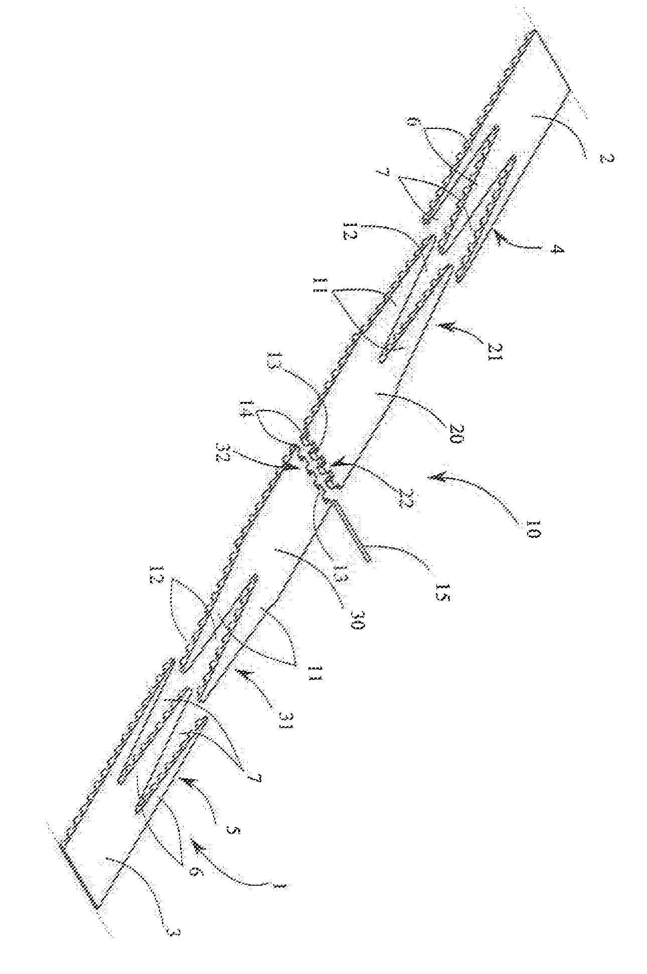
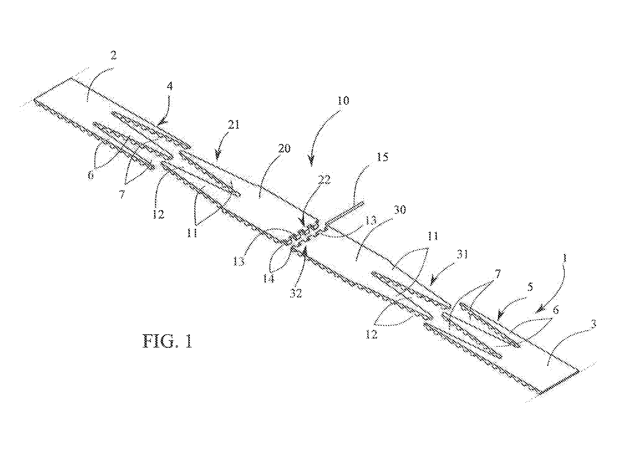
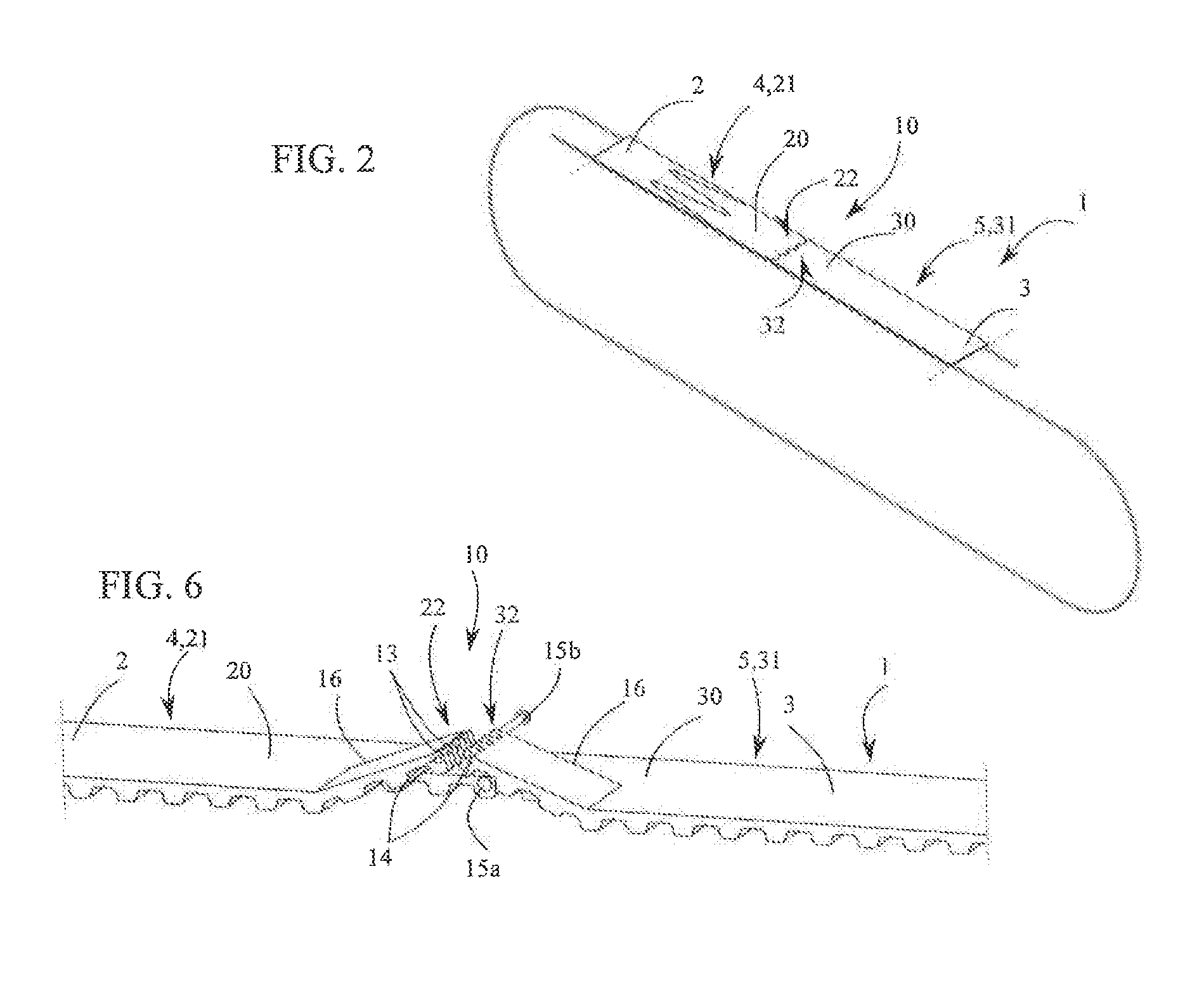
The present invention introduces a splicing device made from a material compatible with that of a material band, having a yield strength similar to that of the material band, while offering high tensile resistance and remaining very flexible. This device offers easy manufacturing, cost-effectiveness, reversibility, and ease of use for the manufacturer, the dealer, and even the customer. The splicing elements have a thermoplastic material compatible with the material band and each contains one or more traction cores embedded in the thermoplastic material. The traction cores extend longitudinally in the splicing elements up to the teeth of each topping and surround the transverse opening of the teeth of each toothing. This results in a splicing device with increased tensile strength. The technical effects of the invention include improved fatigue strength, flexibility, and adaptability to different belt dimensions.

Problems solved by technology

The splicing device described in the above-mentioned publication is made of two spring steel plates that, even though they are positioned in the neutral bending plane of the belt, cause in the splicing area of the belt a bending stiffness that is incompatible with the function of the belt and strongly affects the lifetime of the belt.
Moreover, steel is not compatible with the thermoplastic material of the belt and this is why the splicing elements include recesses to allow the connection. with the thermoplastic material by melting.
Nevertheless, this splicing device roust be manufactured for every belt width, which requires managing a large number of references.
It is indeed not possible to produce this splicing device in only one size that would then be cut to the width and length suitable for the belt to equip.
Moreover, due to its specificity, the assembly of the splicing device at the ends of the belt cannot be entrusted to the dealer or to the end customer.
Therefore this solution is not satisfying.

Method used


Image

  • Splicing device for closing a looped material band and material band provided with such splicing device
  • Splicing device for closing a looped material band and material band provided with such splicing device
  • Splicing device for closing a looped material band and material band provided with such splicing device

Examples


Embodiment Construction

[0004]The present invention aims to remedy these disadvantages by offering a splicing device made in a material compatible with that of the material band, having a yield strength similar to that of the material band, while offering high tensile resistance and remaining very flexible, which ensures it a very high fatigue strength, this device being moreover easy to manufacture, cost-effective, reversible and easy to use for the manufacturer, the dealer and even the customer, to equip any belt, toothed or not, reinforced or not, and easy to adapt in width and / or in length to the dimensions of the belt to equip.

[0005]To that purpose, the invention relates to a splicing device of the kind defined in the preamble, characterized in that the splicing elements are made out of a thermoplastic material compatible with the material of said band and comprise each at least one traction core embedded in said thermoplastic material, said traction core extending longitudinally in said splicing elem...


PUM

PropertyMeasurementUnit
Fractionaaaaaaaaaa
Areaaaaaaaaaaa

Abstract

A splicing device (10) for closing a looped material band (1) comprising two splicing elements (20, 30) intimately linked to the ends (2, 3) of the material band (1), assembled together by fitting two toothings (22, 23) into each other, and locked by a transverse locking rod (15) inserted in the aligned transverse openings (14) of the teeth (13) of each toothing. The splicing elements (20, 30) are made out of a material compatible with that of the material band and comprise a traction core extending longitudinally up to the teeth (13) and surrounding the transverse opening (14) of teeth (13) of each toothing (22, 32) so that, when the splicing device (10) is assembled and locked, the traction cores of the splicing elements ensure the tensile strength of the splicing device (10) while remaining very flexible.

Description

TECHNICAL SCOPE[0001]The present invention relates to a splicing device for closing a looped material band such as in particular a conveyor belt, a power transmission belt or similar, whereby this splicing device comprises two splicing elements provided at one end with an assembly area arranged to be intimately linked respectively to the two longitudinal ends of the material band, and with a toothing at the other end, the toothings being provided respectively in the plane of the splicing elements and having complementary shapes to fit into each other, the teeth of each toothing comprising at least one transverse opening aligned with that of the neighboring teeth, in order to define, when the toothings are fitted into each other, at least one transverse passage arranged to receive at least one locking rod.[0002]The invention also relates to a material band such as in particular a conveyor belt, a power transmission belt or similar, this material band being looped by a splicing device...

Claims


Application Information

Patent Timeline
IPC IPC(8): F16G3/02F16G3/10
CPCF16G3/02Y10T24/1688F16G3/10B29C65/564B29C66/1142B29C66/223B29C66/225B29C66/4324B29C66/72141B29C66/73921B29L2031/709B29L2031/7092B29L2031/7094F16G1/28B65G15/36
Inventor FREY, PIERRE-REGIS
Owner TANALS S
Learn More