Voltage sensor for high and medium voltage use and a method of making the same

a high and medium voltage, voltage sensor technology, applied in the direction of instruments, base element modifications, measurement instrument housings, etc., can solve the problem of high cost of solution

Inactive Publication Date: 2015-12-03
ABB (SCHWEIZ) AG
View PDF12 Cites 4 Cited by
  • Summary
  • Abstract
  • Description
  • Claims
  • Application Information

AI Technical Summary

Benefits of technology

[0014]Exemplary embodiments can reduce manufacturing time and effort and decrease production costs and investments needed for production. By using standard shrinking tube with sheds, which is shrunken around a voltage divider module, significant cost saving in mold investments and reduction in sensor costs as well as significant reduction on manufacturing time of such solution can be realized as mentioned.
[0015]In an exemplary embodiment, the shrinking tube can be placed on the housing of the voltage divider near the distal ends of the housing, and / or at least partly over an output cable of the voltage sensor. An exemplary embodiment is to cover the definite transition area between the housing and the output cable, in order to implement at that place a creepage distance enlargement.
[0016]In an exemplary embodiment, the voltage sensor is located within or surrounded by shielding electrodes, which are arranged inside or outside the voltage divider housing.
[0017]In an exemplary embodiment, the voltage divider part is cast in simple shape and the insulation is done by insulating material; e.g., epoxy, polyurethane or similar.
[0018]According to an exemplary embodiment, the insulating shrinking tube can be provided as a cold shrink tube, by the use of insulating cold shrinking material.
[0019]Alternatively but also advantageous is that the insulating shrinking tube can be provided as a warm shrink tube, by the use of insulating warm shrinking material.
[0020]So the same effect of implementing creepage distance enlargement can be placed on a sensor's housing or cable, in both cases in a very simple way of manufacture.

Problems solved by technology

This solution is expensive and involves investment into a complex mold for casting, such as when the requirement of creepage distance is of importance and ribs on the sensor body are used to achieve given creepage distance, such as in FIG. 1.

Method used


Image

  • Voltage sensor for high and medium voltage use and a method of making the same
  • Voltage sensor for high and medium voltage use and a method of making the same
  • Voltage sensor for high and medium voltage use and a method of making the same

Examples


Embodiment Construction

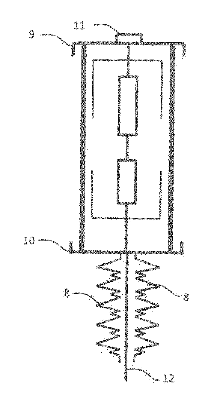
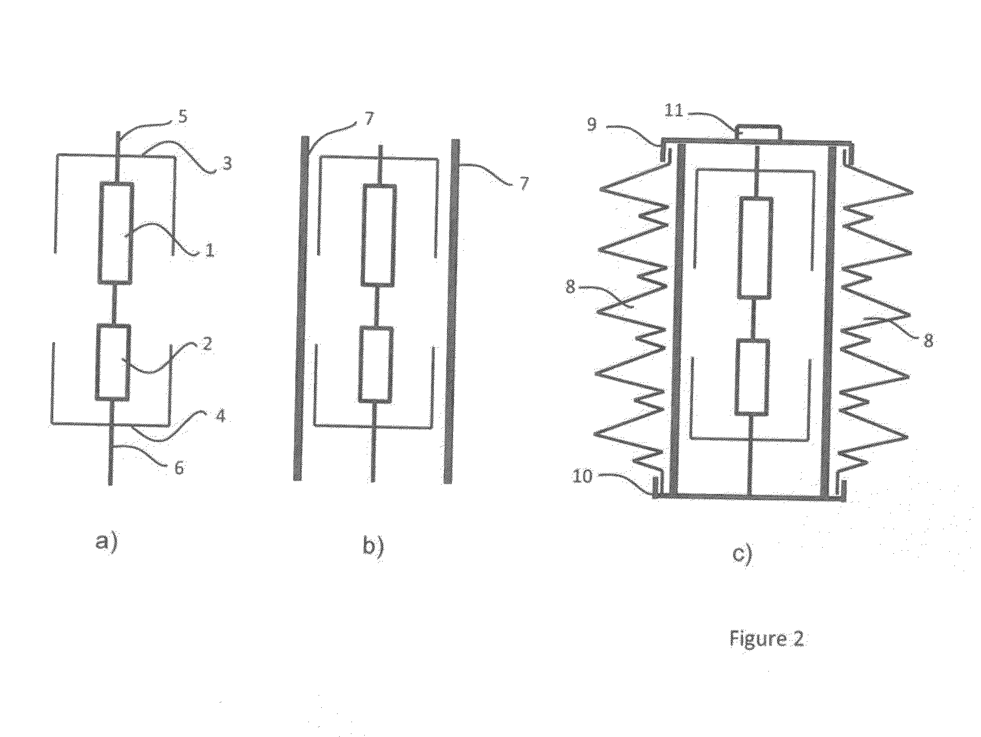
[0011]Structures for creepage distance enlargement are disclosed herein which can be used with a sensor housing in a very effective and easy way.

[0012]According to exemplary embodiments, the voltage divider can be arranged in a housing or in housing modules which is or are covered at least partly by at least one shrinking tube of insulating material such that the shrinking creepage distance enlarging structures are implemented at least at the outer surface of the shrinking tube.

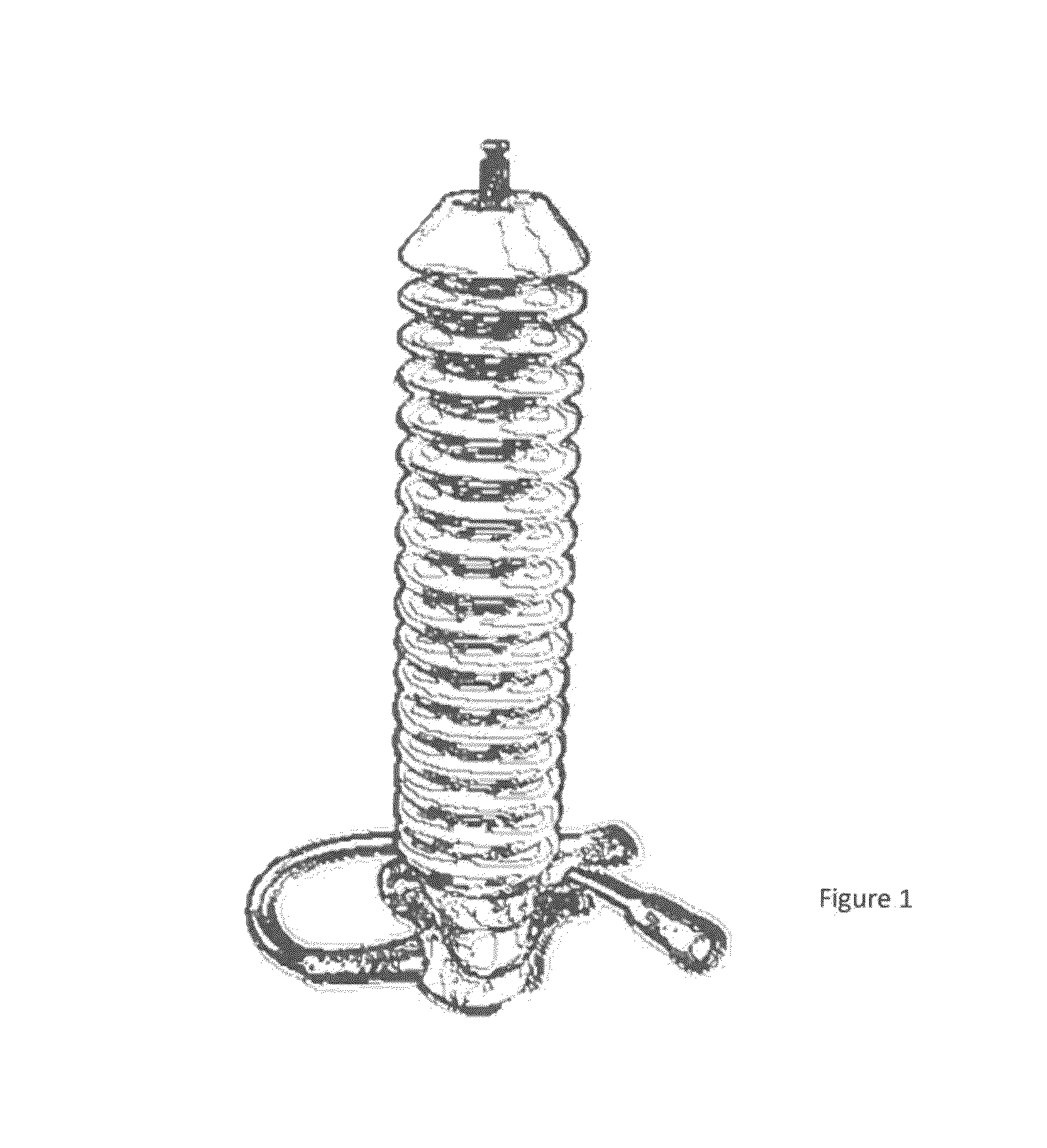
[0013]In exemplary embodiments, a standard shrinking tube with sheds can be used, which is shrunken around a voltage divider module. This solution can provide significant cost saving in mold investments and reduction on sensor costs as well as significant reduction on manufacturing time of such solution.

[0014]Exemplary embodiments can reduce manufacturing time and effort and decrease production costs and investments needed for production. By using standard shrinking tube with sheds, which is shrunken around a...


PUM

PropertyMeasurementUnit
voltageaaaaaaaaaa
creepage distanceaaaaaaaaaa
distanceaaaaaaaaaa

Abstract

A voltage sensor is disclosed for high and medium voltage use, wherein a voltage divider is arranged in a housing with external creepage distance enlarging ribs. To implement structures for creepage path enlargement to a sensor housing in a very effective and easy way, the voltage divider is arranged in a housing or in housing modules which is or are covered at least partly by at least one shrinking tube of insulating material such that the shrinking creepage enlarging structures are implemented at least at outer surface of the shrinking tube.

Description

RELATED APPLICATION[0001]This application claims priority under 35 U.S.C. §119 to European Patent Application No. 14001838.3 filed in Europe on May 27, 2014, the entire content of which is hereby incorporated by reference in its entirety.FIELD[0002]The present disclosure relates to a voltage sensor for high and medium voltage use, and a method of making the same.BACKGROUND INFORMATION[0003]Known voltage sensors use an impedance divider cast in some insulation material (epoxy or polyurethane) in order to withstand voltage stresses on MV or HV lines. This solution is expensive and involves investment into a complex mold for casting, such as when the requirement of creepage distance is of importance and ribs on the sensor body are used to achieve given creepage distance, such as in FIG. 1.SUMMARY[0004]A voltage sensor for high and medium voltage use is disclosed, comprising: a voltage divider arranged in a housing or housing modules with external shrinking creepage distance enlarging s...

Claims


Application Information

Patent Timeline
Patent Type & Authority Applications(United States)
IPC IPC(8): G01R1/04G01R15/16
CPCG01R1/04Y10T29/49009G01R15/16G01R15/04H01H33/66207H01H2033/66223
Inventor JAVORA, RADEK
Owner ABB (SCHWEIZ) AG
Why Eureka
Try Eureka