
Method for producing an electrostatic holding apparatus

a technology of holding apparatus and holding element, which is applied in the direction of lamination, paper/cardboard containers, containers, etc., can solve the problems of deformation deviation of the form of the support surface, and the support surface of the holding element, so as to avoid the disadvantages of conventional techniques, improve the exactness of the support surface, and shorten the production duration

Active Publication Date: 2015-12-03
ASML NETHERLANDS BV
View PDF5 Cites 11 Cited by
  • Summary
  • Abstract
  • Description
  • Claims
  • Application Information

AI Technical Summary

Benefits of technology

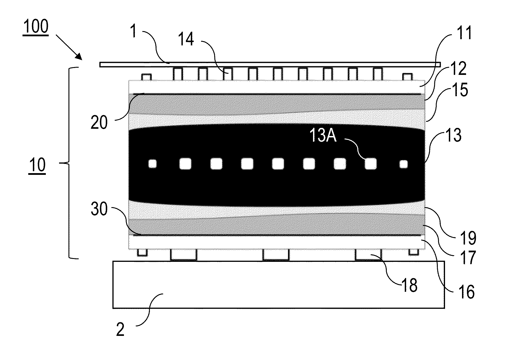
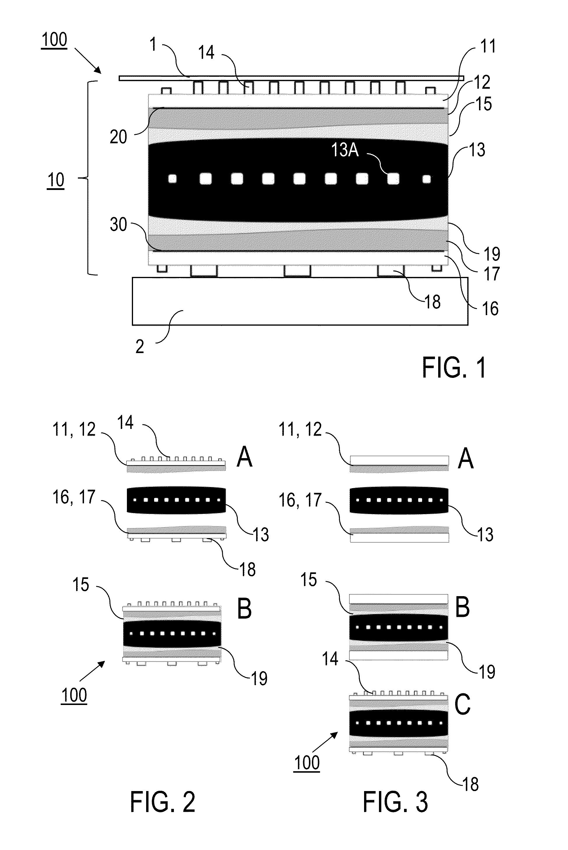
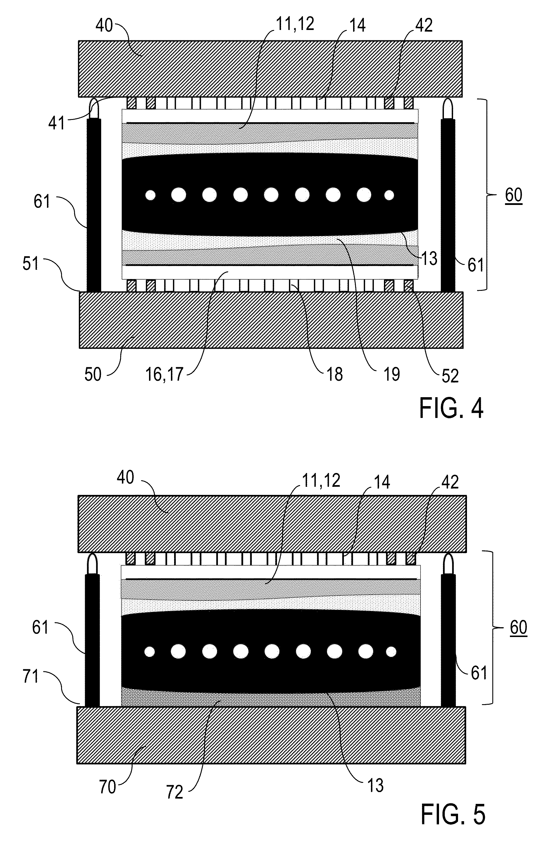
The invention provides an improved method for producing an electrostatic holding apparatus that avoids disadvantages of conventional techniques. The method simplifies the production process and reduces the time required for production. The apparatus has a high degree of form accuracy and is easy to align. The invention also provides an improved electrostatic holding apparatus that avoids disadvantages of conventional holding apparatuses. The apparatus has a support surface that is formed by the first holding element and the core element, with no deformation in the support surface during the curing process. The thickness of the adhesive connecting layer is small, which improves the adhesive connection and the thermal coupling between the core element and the first holding element. The first holding element can be aligned on a reference plate and then connected to the core element, resulting in a stress-free mounting that improves the holding apparatus's mechanical and thermal stability. The holding apparatus is designed for holding silicon wafers and has burls on its surface to improve the support of the component. The first and second holding elements can be aligned simultaneously, and the working distance between the first forming tool and the second forming tool allows for easier alignment.

Problems solved by technology

The conventional holding apparatus has the disadvantage that the form of the support surface of the holding element follows the surface form of the core element, as a result of being connected to the core element by anodic bonding.
However, the core element may have form deviations from the desired form of the support surface, in particular from a flat form, such that the support surface also becomes deformed by the anodic bonding.
Consequently, in the case of the conventional electrostatic holding apparatus, deviations in the form of the support surface, for example from the desired planarity, may occur, that have a disadvantageous effect upon the semiconductor processing of the silicon wafer, in particular in the exposure of the latter.
Hitherto, it has only been possible to avoid these problems by elaborate processes for setting the planarity, this having a disadvantageous effect upon the duration of production.
The said disadvantage occurs, not only in the case of electrostatic holding apparatuses for silicon wafers, but generally in the case of all holding apparatuses whose use requires a support surface of highly exact form.

Method used


Image

  • Method for producing an electrostatic holding apparatus
  • Method for producing an electrostatic holding apparatus
  • Method for producing an electrostatic holding apparatus

Examples


Embodiment Construction

[0009]Provided according to a first general aspect of the invention is a method for producing a holding apparatus for electrostatically holding a component such as, for example, a silicon wafer, wherein a plate-type first holding element (upper holding element), which has a first electrode device (upper electrode device) and which spans a support surface for receiving the component, and a plate-type core element are connected to each other. According to the invention, the first holding element and the core element are adhesive-bonded to each other. A liquid adhesive is used, which is hardened (for example, by polymerization) by means of, for example, a chemical transformation process and / or a heating process. The first holding element is aligned with a first forming tool (upper forming tool), wherein the support surface of the first holding element is matched to a predetermined master surface (or master forming surface) of the first forming tool. The support surface of the first hol...


PUM

PropertyMeasurementUnit
Thicknessaaaaaaaaaa
Shrinkageaaaaaaaaaa
Thicknessaaaaaaaaaa

Abstract

Production of a holding apparatus (100) for electrostatically holding a component, e.g., silicon wafer (1), includes connecting plate-type first holding element (11, 12) and plate-type core element (13), first holding element (11, 12) having first electrode device (20) and spanning support surface for receiving component (1), and the connecting includes the steps: providing liquid adhesive to at least one of the mutually facing surfaces of first holding element (11, 12) and core element (13), aligning first holding element (11, 12) with first forming tool (40) such that support surface is matched to predetermined master surface (41) of first forming tool (40), and curing the adhesive, wherein first adhesive connecting layer (15) is formed, which has thickness variations constituted by form deviations between support surface and at least one of the mutually facing surfaces. Also described is a holding apparatus (100) configured to electrostatically hold a component, e.g., silicon wafer (1).

Description

BACKGROUND OF THE INVENTION[0001]The invention relates to a method for producing a holding apparatus designed to electrostatically hold a component, in particular a silicon wafer. The invention also relates to a holding apparatus produced by this method. Applications of the invention are in the production of devices or tools for holding components by means of electrostatic forces, in particular for holding semiconductor components such as, for example, silicon wafers.[0002]Holding apparatuses for holding components electrostatically, which are also referred to as electrostatic holding apparatuses, electrostatic clamping apparatuses, electrostatic clamps, ESCs or electrostatic chucks, are known in general. An important application of electrostatic holding apparatuses is in holding silicon wafers in lithographic semiconductor processing, for example in chip production, in which particular advantages of electrostatic holding that are exploited are ease of switching of electrostatic hol...

Claims


Application Information

Patent Timeline
IPC IPC(8): H01L21/683
CPCY10T156/10H01L21/6833H01L21/6831
Inventor STEIN, ALEXANDER
Owner ASML NETHERLANDS BV
Learn More