Integrated antenna for electronic device

Inactive Publication Date: 2015-12-03
NASH PHIL
View PDF1 Cites 8 Cited by
  • Summary
  • Abstract
  • Description
  • Claims
  • Application Information

AI Technical Summary

Benefits of technology

The present invention is an improved antenna element or array that can be used for media and computing devices. It is large enough to provide high gain and exceptional bandwidth. The device can be positioned close to the electronic component and transmit RF signals. It can also send and receive RF signals on multiple bandwidths simultaneously without any holes in the radiation pattern. The device is easy to retrofit and can be part of or engageable with the housing of the electronic device. It performs equally well in all frequency ranges and can be positioned for more gain without being obstructed by the device's positioning within a computer cabinet or the like during use. The disclosed device is integrated into the computer hardware structure, which excites the entire hardware and radiates more energy compared to smaller prior art antennas. This results in successful communication with other devices at further distances and higher throughput of data due to the improved signal generated and received. A large format in a wideband configuration can be formed on a dialectic-separated portion of the housing or on a substrate engageable with a non-metal housing.

Problems solved by technology

However, because of the cramped conditions and design considerations of mounting an antenna or board-engaged antenna, such antennas typically have electrical lengths of one-half wavelength at the midband frequency in the WiFi band.
Such positioning and mounting inherently cause problems with reception and transmission of RF communications.
This is because many computers and electronic devices have metal cases which block or severely inhibit reception.
Further the antenna being small and formed for a half wavelength or less, at the midband frequency of the radio band being used such WiFi or BlueTooth, does not perform well when the frequencies vary too far from that midband since the small antenna is adapted for best reception in that realm of the spectrum.
As can be discerned, the combination of a center-weighted antenna, placed within a metal case, can combine to significantly inhibit the ability to transmit and receive RF signals on the desired frequency, especially if the area of the band being employed, is distanced from the center.
These shortcomings result in poor signal gain, directional transmission and reception, holes in the radiation pattern, slow digital throughput due to such weak or varying signals.
Thus, while techniques are currently available, challenges exist.

Method used


Image

  • Integrated antenna for electronic device
  • Integrated antenna for electronic device
  • Integrated antenna for electronic device

Examples


Embodiment Construction

[0032]The present invention relates to antennas for transmission and reception of radio frequency communications. More particularly, it relates to a device and method for positioning antennas on surfaces encasing or surrounding an electronic device such as the rear of a laptop computer, smartphone, or pad computer, or on plates, covers, and components which removably engage with such devices.

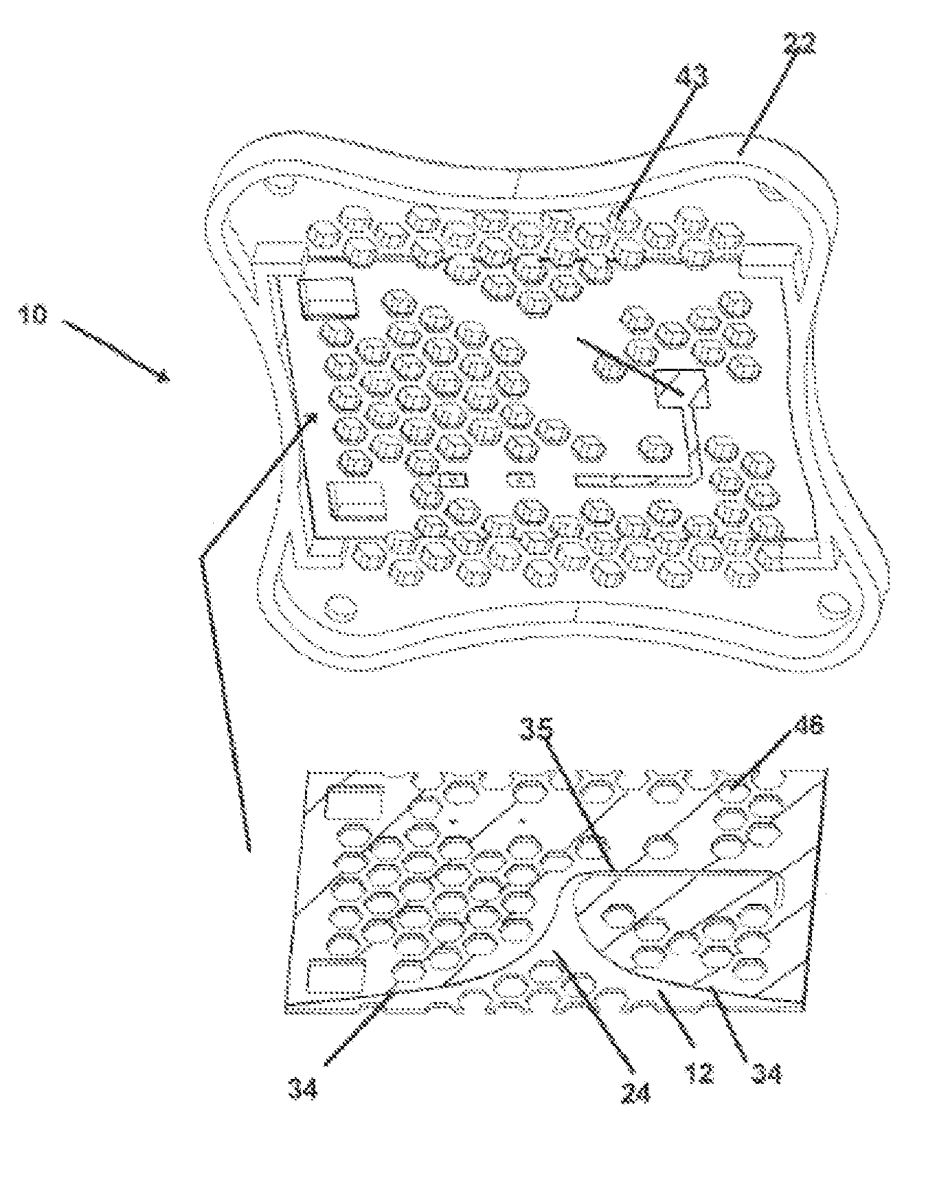
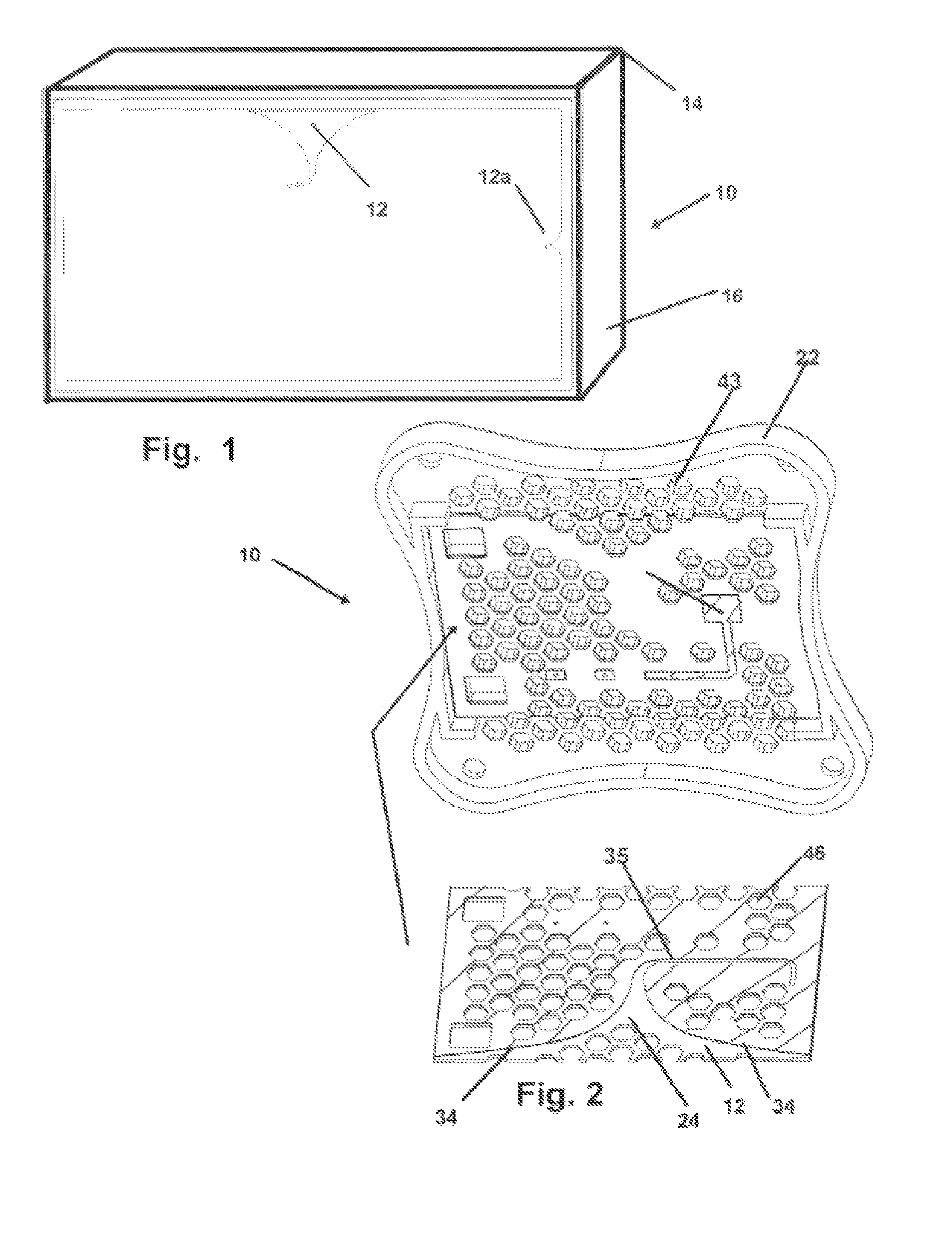
[0033]Now referring to drawings in FIGS. 1-4, wherein similar components are identified by like reference numerals, there is seen in FIG. 1 an exemplar of a mode of the device 10 and method herein wherein the antenna 12 has been formed directly into a large area of a metal case or housing 14, surrounding an electronic device 16 such as a computer or server or television or the like which employs RF communications such as WiFi or Bluetooth.

[0034]It is one of the primary objectives of the disclosed method and invention to make employ the large areas of the metal material which encase and surround ...


PUM

PropertyMeasurementUnit
Areaaaaaaaaaaa

Abstract

Systems and methods for providing antennas for transmission and reception of radio frequency communications. At least some implementations relate to a device and method for positioning antennas on surfaces encasing or surrounding an electronic device such as the rear of a laptop computer, smartphone, or tablet computer, or on plates, covers, and / or components that removably engage with such devices.

Description

RELATED APPLICATIONS[0001]This application claims priority to U.S. Provisional Patent Application Ser. No. 61 / 992,068 (Attorney Docket No. 11072.728) filed May 12, 2014, entitled INTEGRATED ANTENNA FOR ELECTRONIC DEVICE, which is incorporated herein by reference in its entirety.BACKGROUND OF THE INVENTION[0002]1. Field of the Invention[0003]The present invention relates to antennas for transmission and reception of radio frequency communications. More particularly, it relates to a device and method for positioning antennas on surfaces encasing or surrounding an electronic device such as the rear of a laptop computer, smartphone, or pad computer, or on plates, covers, and components which removably engage with such devices.[0004]2. Background and Related Art[0005]Some computers and electronic devices in recent years include internal antennas for the broadcast and reception of RF wireless signals such as Bluetooth and WiFi. However, because of the cramped conditions and design conside...

Claims


Application Information

Patent Timeline
IPC IPC(8): H01Q1/24
CPCY10T29/4902H01Q1/24H01Q1/243
Inventor NASH, PHIL
Owner NASH PHIL
Why Eureka
Try Eureka