User Defined Objects for Network Devices

a network device and user-defined technology, applied in the field of data networks, can solve the problems of not being able to offer a one-size-fits-all or gold-silver-bronze type of network service policy to accommodate many client needs in the data network, and limiting issues for the service provider as well as the client,

Active Publication Date: 2015-12-03
A10 NETWORKS
View PDF4 Cites 53 Cited by
  • Summary
  • Abstract
  • Description
  • Claims
  • Application Information

AI Technical Summary

Benefits of technology

[0008]This summary is provided to introduce a selection of concepts in a simplified form that are further described in the Detailed Description below. This summary is not intended to identify key features or essential features of the claimed subject matter, nor is it intended to be used as an aid in determining the scope of the claimed subject matter.

Problems solved by technology

Though it is common for a service provider to allow the clients to download and to run client software on the provided servers, it is not possible for the clients to download client software or instructions onto the network devices within the data network.
This limitation presents issues to the service provider as well as the clients.
As there are many clients and each client has different needs, it is impossible for the service provider to offer a one-size-fits-all or a gold-silver-bronze type of network service policy to accommodate many client needs in the data network.

Method used


Image

  • User Defined Objects for Network Devices
  • User Defined Objects for Network Devices
  • User Defined Objects for Network Devices

Examples


Embodiment Construction

[0028]The following detailed description includes references to the accompanying drawings, which form a part of the detailed description. The drawings show illustrations in accordance with example embodiments. These example embodiments, which are also referred to herein as “examples,” are described in enough detail to enable those skilled in the art to practice the present subject matter. The embodiments can be combined, other embodiments can be utilized, or structural, logical, and electrical changes can be made without departing from the scope of what is claimed. The following detailed description is therefore not to be taken in a limiting sense, and the scope is defined by the appended claims and their equivalents.

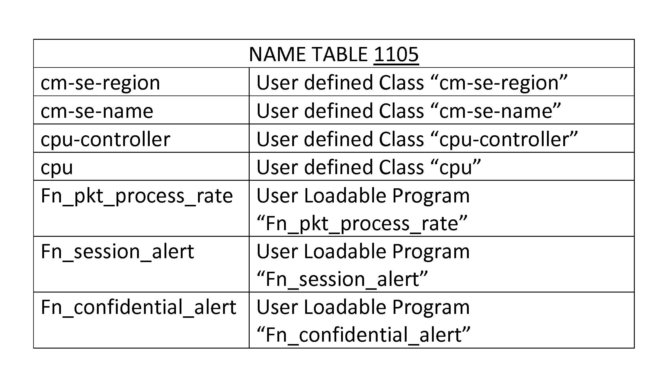
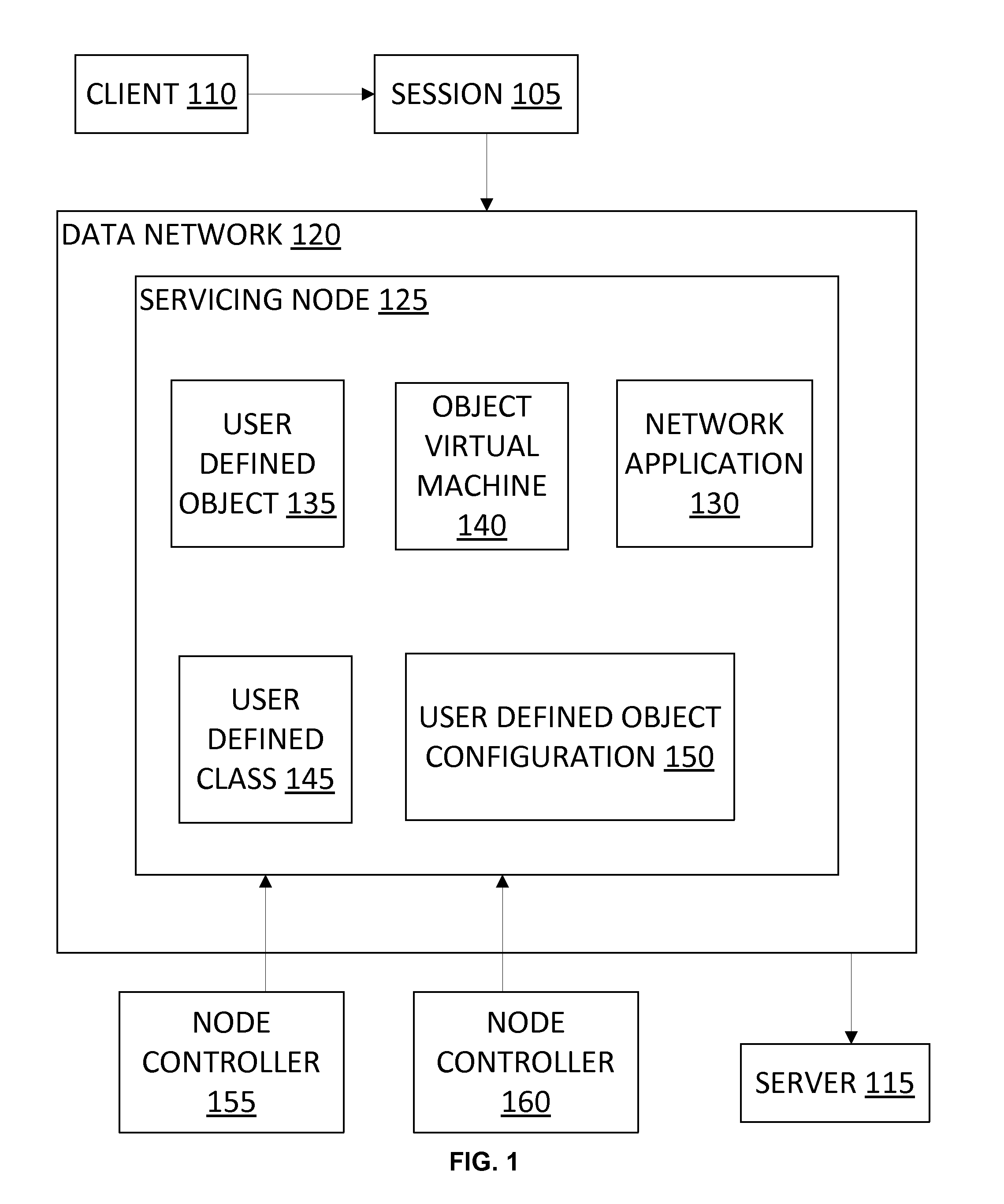
[0029]FIG. 1 illustrates an exemplary embodiment of a servicing node processing a service session 105 (also referred to herein as session 105) between a client 110 and a server 115. In various embodiments, client 110 conducts a session 105 with server 115 over data netw...


PUM


Abstract

Systems and methods are provided herein. An exemplary servicing node may include: an interface to a data network, the interface coupled to an object machine; and the object machine, the object machine: receiving a data packet from the data network using the network interface, the data packet comprising at least one of a destination address, a destination port number, and an application protocol; determining a condition associated with the at least one of the destination address, the destination port number, and the application protocol; identifying a program name using the condition; executing a program using a name table, the name table linking each of a plurality of program names to a respective program, the executing comprising getting an instruction of the program, the instruction including object information.

Description

CROSS-REFERENCE TO RELATED APPLICATIONS[0001]The present application is a continuation-in-part and claims the priority benefit U.S. patent application Ser. No. 14 / 492,465 filed Sep. 22, 2014 and entitled “Programming a Data Network Device Using User Defined Scripts with Licenses, which in turn is a continuation-in-part and claims the priority benefit of U.S. patent application Ser. No. 14 / 295,265 filed Jun. 3, 2014 and entitled “Programming a Data Network Device Using User Defined Scripts.” The disclosures of the above-referenced patent applications are incorporated herein by reference for all purposes.BACKGROUND OF THE INVENTION[0002]1. Field of the Invention[0003]The present invention relates generally to data networks, and more particularly, to a data network being programmed using user defined objects.[0004]2. Description of the Related Art[0005]In a typical network deployment scenario, a company, such as a service provider or a corporation, constructs a data network by purchasi...

Claims


Application Information

Patent Timeline
Patent Type & Authority Applications(United States)
IPC IPC(8): H04L12/26H04L29/08
CPCH04L67/10H04L43/0876H04L41/0233H04L41/0895H04L41/0894H04L41/0893
Inventor SAMPAT, RISHIJALAN, RAJKUMAR
Owner A10 NETWORKS
Why Eureka
Try Eureka