Supercharge Your Innovation With Domain-Expert AI Agents!

Method for Manufacturing Faucet and Faucet Produced Thereby

a manufacturing method and technology for faucets, applied in valve housings, other domestic objects, mechanical devices, etc., can solve the problems of affecting the quality of the finished product, the inability to mold, and the inability to manufacture, so as to reduce the manufacturing cos

Inactive Publication Date: 2015-12-10
JCL IND CO LTD
View PDF3 Cites 2 Cited by
  • Summary
  • Abstract
  • Description
  • Claims
  • Application Information

AI Technical Summary

Benefits of technology

The present invention aims to provide a method for manufacturing a faucet that can reduce manufacturing costs, prevent harmful components from being supplied to the user, and improve productivity through double injection molding while decreasing failure rates in the manufacturing process.

Problems solved by technology

However, the molding work for making the body of the faucet may cause serious environmental pollution, and further, harmful components (graphite and impurities) may remain on the body of the faucet according to the characteristics of the molding work, so that when the faucet is used as a product, the harmful components may be mixed with the water discharged from the faucet.
Additionally, since the molding work for the faucet is generally conducted in weak circumstances, manufacturers are reluctant to do the molding work.
On the other hand, while the body of the faucet is being used as a product for a long period of time, it may be decayed to a higher degree than that of the body of the faucet as an initial product due to tap water, thus causing serious sanitary problems.
When hot water is used, moreover, heat is fast transmitted to the faucet body made of brass, and at this time, if the old and the weak or the children are contacted with the hot faucet body, they may easily get burnt.
Since the faucet made of the synthetic resin does not have any molding work, it can solve the above-mentioned problems and can be easily made, thus enhancing the manufacturing cost and the productivity, but while the faucet made of the synthetic resin is being frequently contacted with cool and hot water, harmful components of the synthetic resin may be supplied to a user, in the state of being contained in the cool and hot water, due to the chemical reaction with chlorine contained in water.

Method used


Image

  • Method for Manufacturing Faucet and Faucet Produced Thereby
  • Method for Manufacturing Faucet and Faucet Produced Thereby
  • Method for Manufacturing Faucet and Faucet Produced Thereby

Examples


first embodiment

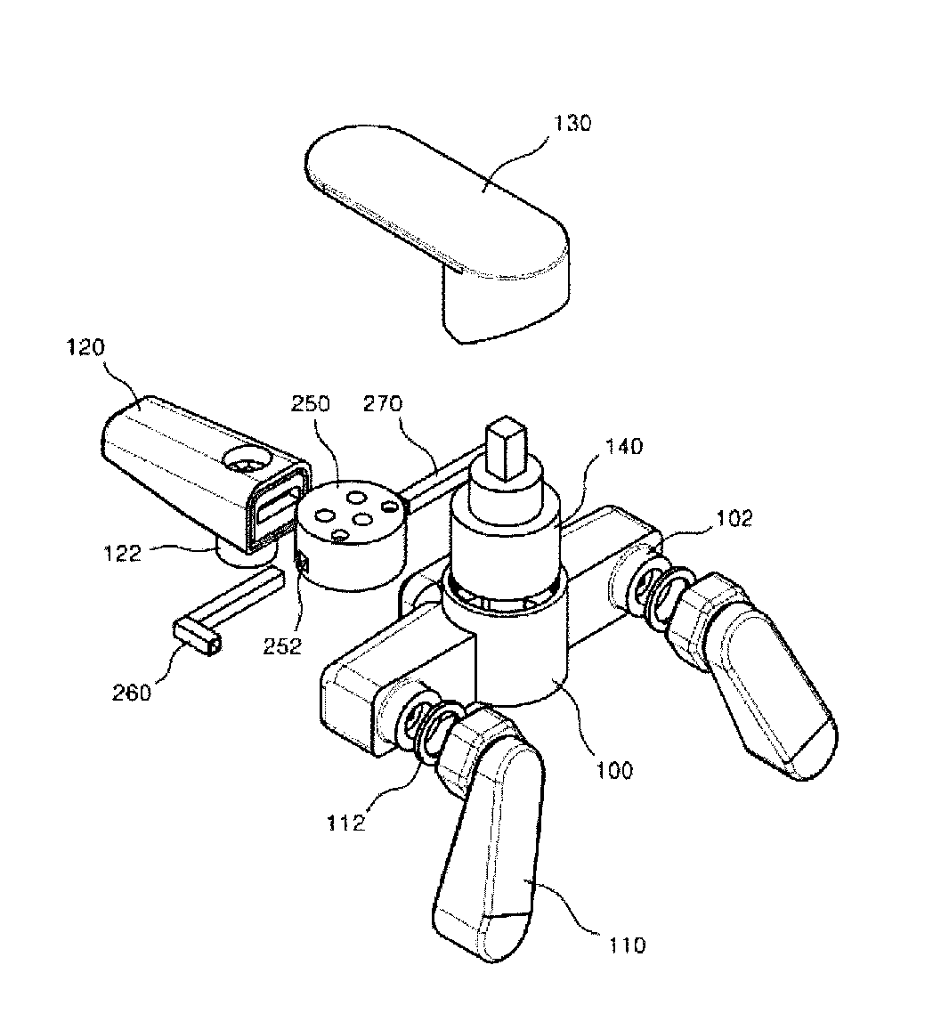
[0044]FIGS. 1 and 2 are exploded perspective views showing a faucet manufactured by a method for manufacturing the faucet according to a first embodiment of the present invention and FIG. 6 is a flow chart showing the method for manufacturing the faucet according to the first embodiment of the present invention. At this time, the corresponding parts in FIGS. 1 and 2 are indicated by corresponding reference numerals.

[0045]Referring to FIGS. 1 and 2, a method for manufacturing a faucet according to a first embodiment of the present invention includes part preparing step S11, cool and hot water flow path pipe coupling step S12, double injection molding step S13, and assembling step S14.

[0046]First, parts for manufacturing a faucet are prepared (at step S11). At this time, the parts include metallic parts and non-metallic parts. The metallic parts include a pair of eccentric sets 110 connected to cool and hot water pipes (not shown) installed on a wall surface, a discharging pipe 120 di...

second embodiment

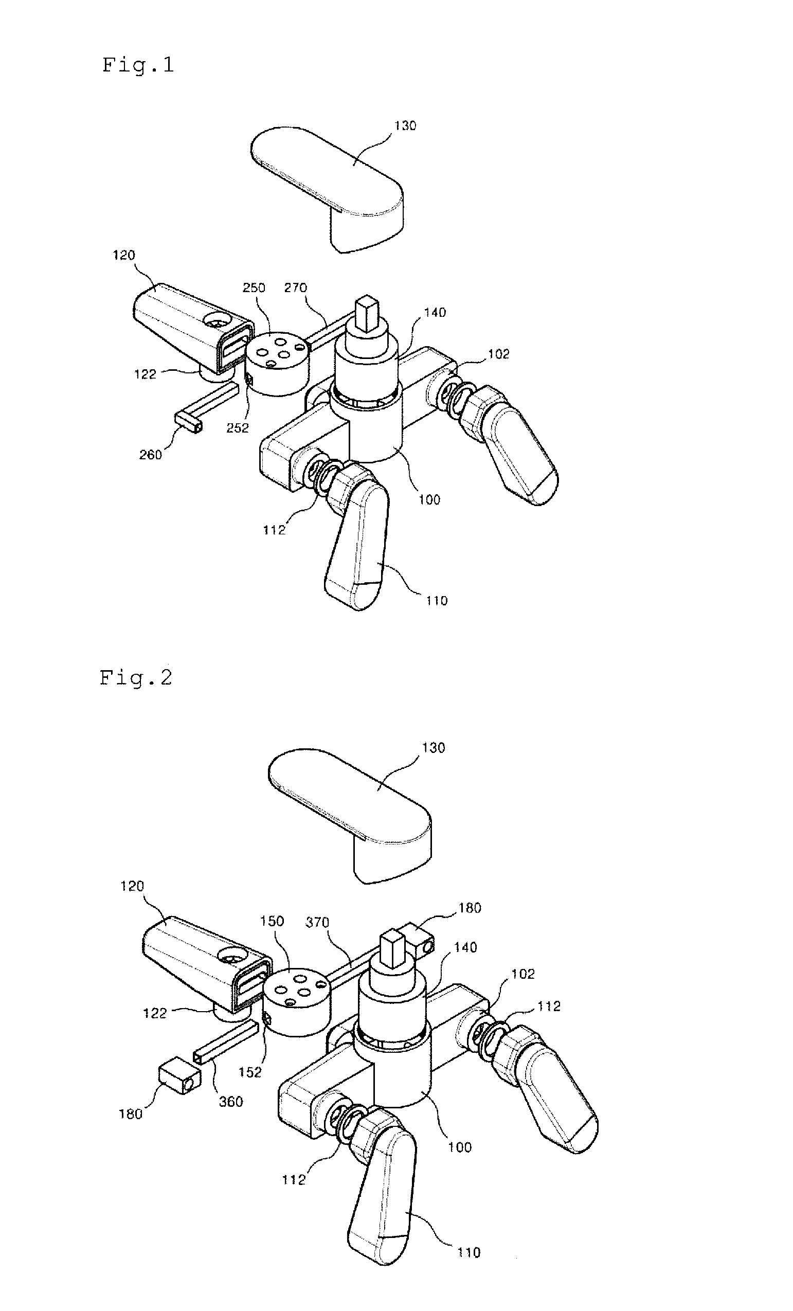
[0066]FIG. 3 is an exploded perspective view showing a faucet manufactured by a method for manufacturing the faucet according to a second embodiment of the present invention. At this time, the corresponding parts in FIG. 3 to those in FIGS. 1 and 2 are indicated by corresponding reference numerals to each other.

[0067]In the same manner as in the first embodiment of the present invention, a method for manufacturing a faucet according to a second embodiment of the present invention includes the part preparing step, the cool and hot water flow path pipe coupling step, the double injection molding step, and the assembling step.

[0068]In the part preparing step, first, metallic parts and non-metallic parts are prepared.

[0069]The metallic parts include eccentric sets 110, a discharging pipe 120, a water outlet 122, and an opening / closing lever 130.

[0070]On the other hand, the non-metallic parts include a controlling member 140, a manifold 250, a cool water flow path pipe 560, and a hot wat...

third embodiment

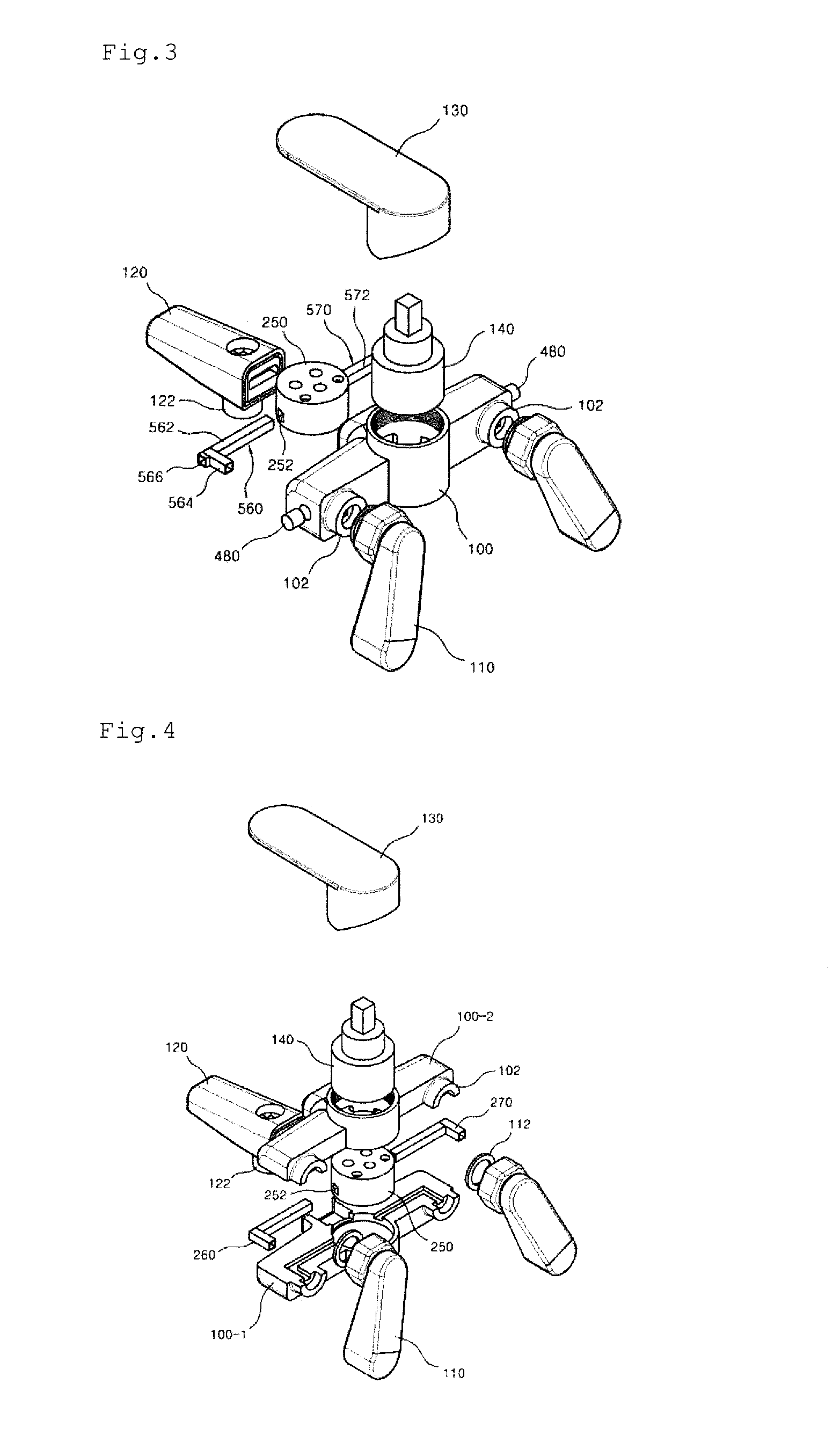
[0089]FIGS. 4 and 5 are exploded perspective views showing a faucet manufactured by a method for manufacturing the faucet according to a third embodiment of the present invention. At this time, the corresponding parts in FIGS. 4 and 5 to those in FIGS. 1 and 2 are indicated by corresponding reference numerals to each other.

[0090]In the same manner as in the first embodiment of the present invention, a method for manufacturing a faucet according to a third embodiment of the present invention includes the part preparing step, the cool and hot water flow path pipe coupling step, the double injection molding step, and the assembling step.

[0091]In the part preparing step, first, metallic parts and non-metallic parts are prepared.

[0092]The metallic parts include eccentric sets 110, a discharging pipe 120, a water outlet 122, and an opening / closing lever 130.

[0093]The non-metallic parts include a controlling member 140, manifolds 150 and 250, cool water flow path pipes 260 and 360, hot wat...


PUM


Abstract

The present invention relates to a method for manufacturing a faucet including the steps of: preparing metallic parts and non-metallic parts, the non-metallic parts having a manifold, and cool and hot water flow path pipes; coupling the cool and hot water flow path pipes to the manifold or coupling the cool and hot water flow path pipes to flow connection members and the manifold; molding the manifold in such a manner as to inject a liquid type ABS resin into a space portion of a double injection mold and to fill the space portion with the ABS resin, so that the manifold to which the cool and hot water flow path pipes are coupled is surrounded with a body; and assembling the body in which the manifold coupled to the cool and hot water flow path pipes is accommodated to other parts constituting the faucet.

Description

RELATED APPLICATIONS[0001]This application claims the benefit of Korean 1 application 10-2014-0068078 filed on Jun. 5, 2014 and entitled “Method for Manufacturing Faucet and Faucet Produced Thereby,” the content of which is hereby incorporated by reference in its entirety and for all purposes.BACKGROUND OF THE INVENTION[0002]1. Field of the Invention[0003]The present invention relates to a method for manufacturing a controlling valve (hereinafter, which is referred to as ‘faucet’), and more particularly, to a method for manufacturing a faucet mounted on a wash basin, bathtub, shower, and kitchen sink to supply water therefrom and to a faucet produced by the method.[0004]2. Background of the Related Art[0005]Generally, a faucet is mounted on a wash basin, bathtub, shower, and kitchen sink to supply hot and cool water to a user, while being cooperatively operated with a boiler.[0006]That is, the faucet is connected to the front end portions of buried cool and hot water pipes, irrespec...

Claims


Application Information

Patent Timeline
IPC IPC(8): E03C1/04
CPCY10T29/49432E03C1/0404F16K11/074F16K11/14F16K27/045E03C1/042
Inventor LEE, JAE CHUN
Owner JCL IND CO LTD
Features
  • R&D
  • Intellectual Property
  • Life Sciences
  • Materials
  • Tech Scout
  • Unparalleled Data Quality
  • Higher Quality Content
  • 60% Fewer Hallucinations
Learn More