
Air conditioning apparatus

Inactive Publication Date: 2015-12-10
UNIMICRON TECH CORP
View PDF3 Cites 7 Cited by
  • Summary
  • Abstract
  • Description
  • Claims
  • Application Information

AI Technical Summary

Benefits of technology

The invention is an air conditioning system that saves energy and meets the need for large airflow. It uses a device to import air from outside the system and creates a vacuum to accelerate the airflow through the system. The air is then adjusted to the required temperature and humidity using a heater and humidifier. To prevent a sudden increase in pressure and potential shock when the air flows out of the system, the system also includes a connecting device to increase the air flow rate and a device near the outlet to maintain low pressure. This ensures a smooth airflow through the system.

Problems solved by technology

However, the freezing method consumes a great deal of electricity and requires refrigerant circulation.
Although the piezoelectric method requires much less electrical energy, the generated airflow is insufficient for industries that require large airflow.

Method used


Image

  • Air conditioning apparatus
  • Air conditioning apparatus
  • Air conditioning apparatus

Examples


Embodiment Construction

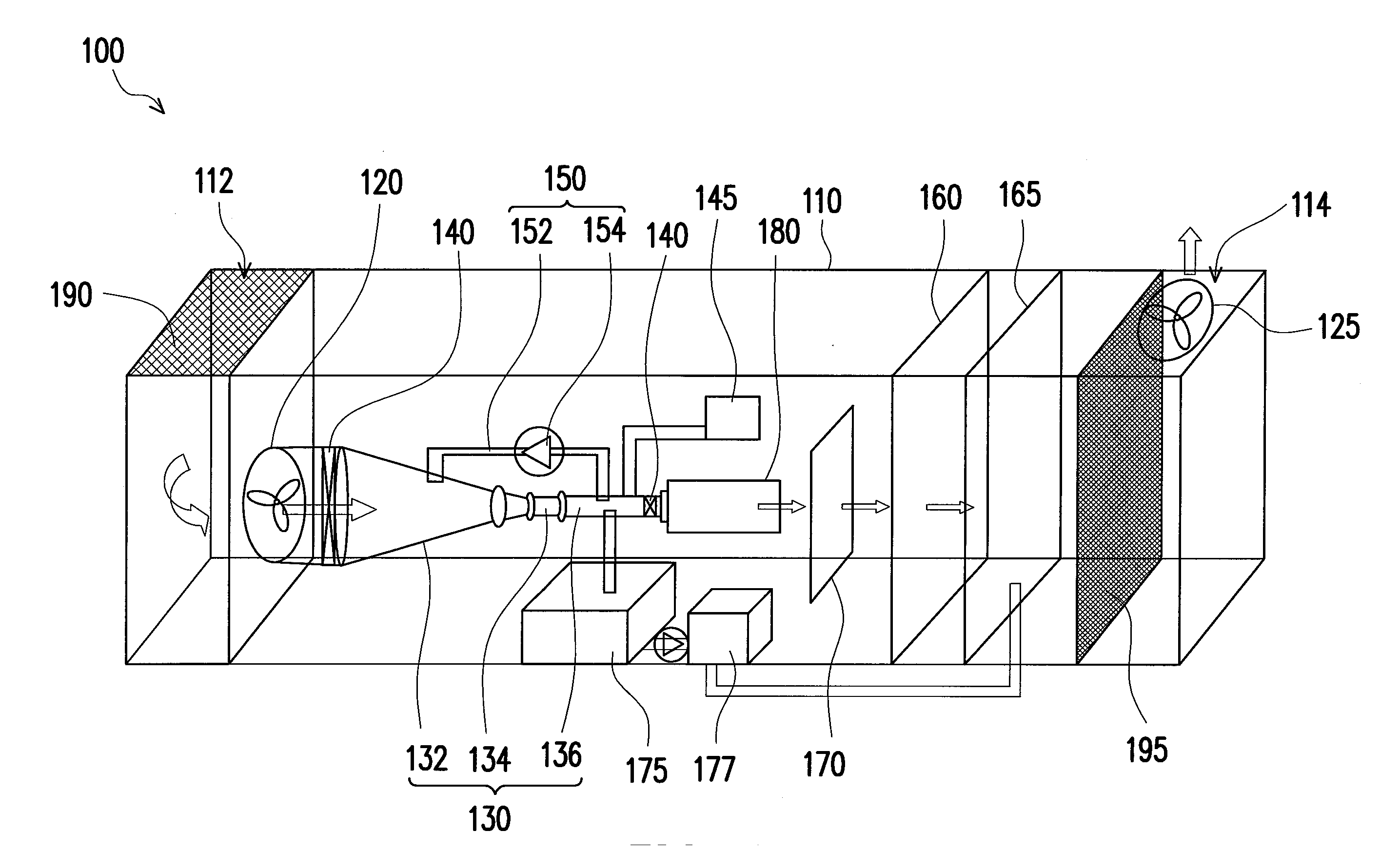
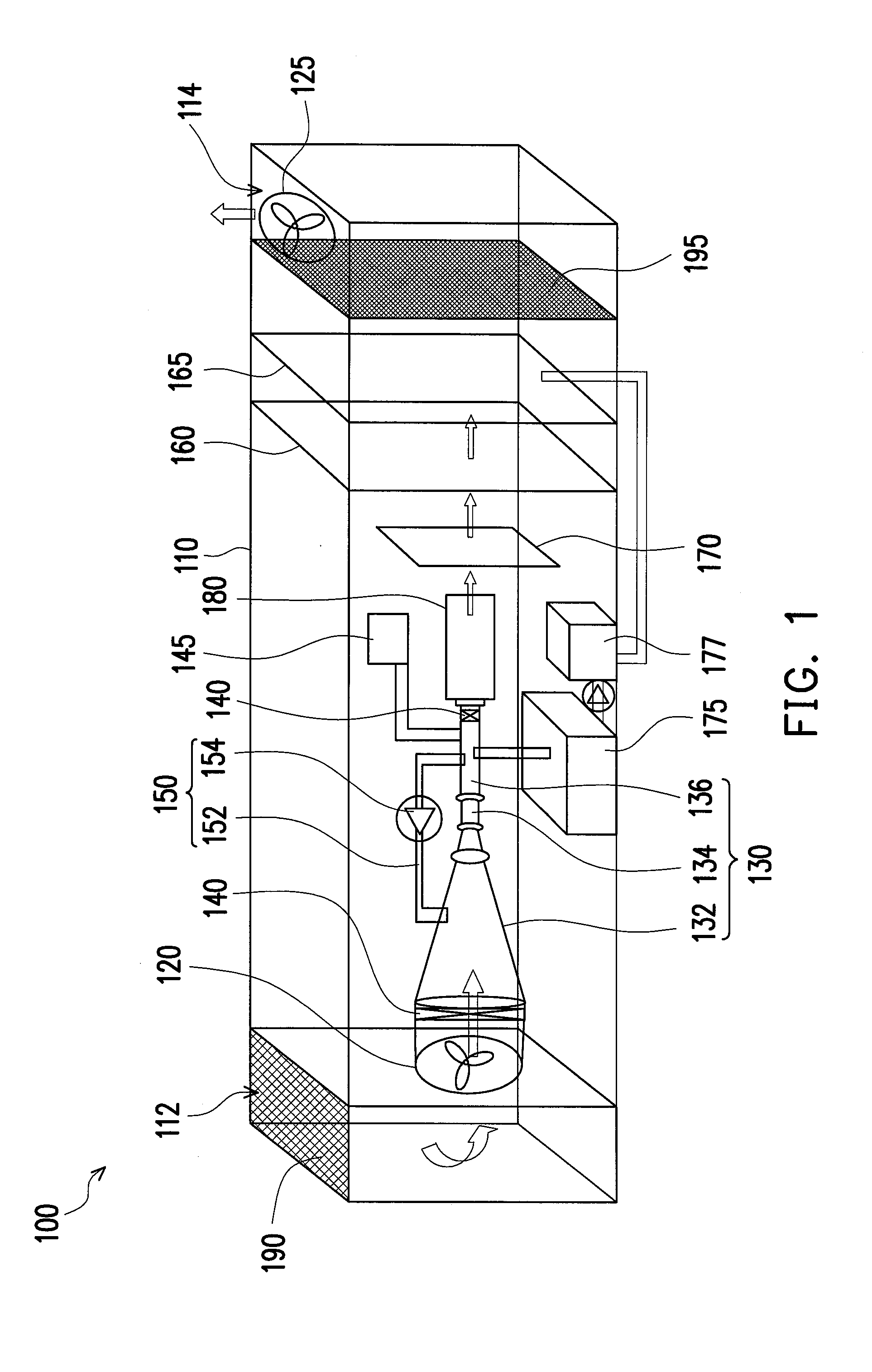
[0024]FIG. 1 is a schematic view of an air conditioning apparatus according to an embodiment of the invention. With reference to FIG. 1, an air conditioning apparatus 100 of this embodiment includes a casing 110, an airflow import device 120, a supersonic nozzle 130, two valves 140, a vacuum pump 145, a connecting device 150, a heater 160, a humidifier 165, and an airflow export device 125.

[0025]The casing 110 has an inlet 112 and an outlet 114. In this embodiment, the inlet 112 and the outlet 114 are respectively located near two sides of the casing 110 and on top of the casing 110, as shown in FIG. 1. However, it is noted that the positions of the inlet 112 and the outlet 114 may be varied according to the actual requirements. For example, the inlet 112 and the outlet 114 may be disposed on the left and the right sides of the casing 110 in FIG. 1. Nevertheless, the invention is not limited to the above.

[0026]The airflow import device 120 is disposed at a position near the inlet 11...


PUM

PropertyMeasurementUnit
Fractionaaaaaaaaaa
Pressureaaaaaaaaaa
Flow rateaaaaaaaaaa

Abstract

An air conditioning apparatus includes a casing having an inlet and an outlet, an airflow import device, a nozzle, two valves disposed at two ends of the nozzle, a vacuum pump connected through the nozzle, a connecting device, a heater, a humidifier, and an airflow export device. The airflow import and export devices are disposed at positions near the inlet and the outlet inside the casing. The nozzle includes an intake portion, a throat, and an exhaust portion connected sequentially and coaxially. A cross-sectional area of the intake portion decreases gradually from one end away from the throat to the other end close to the throat. A cross-sectional area of the throat is smaller than that of the exhaust portion. The connecting device is connected to the intake portion and the exhaust portion. The heater and the humidifier are disposed between the nozzle and the outlet.

Description

BACKGROUND OF THE INVENTION[0001]1. Field of the Invention[0002]The invention relates to an air conditioning apparatus and more particularly relates to an air conditioning apparatus that is energy-saving and meets the demand for large airflow.[0003]2. Description of Related Art[0004]Air conditioning equipment is mainly used for controlling ambient air temperature, humidity, air cleanliness, and air circulation. The current air conditioning equipment achieves the above purposes by a freezing or piezoelectric method.[0005]The freezing method is to evaporate or condense a refrigerant through operation of a compressor, so as to evaporate or condense the ambient air to change the temperature or humidity. However, the freezing method consumes a great deal of electricity and requires refrigerant circulation. In the eco-friendly era, research on the energy-saving procedure has reached its bottleneck. The piezoelectric method is to create a temperature difference above and below the material...

Claims


Application Information

Patent Timeline
IPC IPC(8): F24H3/02F24F6/00
CPCF24H3/022F24F2006/008F24F6/00F24F6/12F24D5/02F24D2200/08
Inventor LIAW, BEEN-WEILIN, HAU-CHIEH
Owner UNIMICRON TECH CORP
Learn More