Eureka AIR delivers breakthrough ideas for toughest innovation challenges, trusted by R&D personnel around the world.

An acoustically optimized air inlet

Active Publication Date: 2015-12-17
SN DETUDE & DE CONSTR DE MOTEURS DAVIATION S N E C M A
View PDF7 Cites 4 Cited by
  • Summary
  • Abstract
  • Description
  • Claims
  • Application Information

AI Technical Summary

Benefits of technology

The patent aims to find a way to reduce the noise caused by an airplane engine's fan, specifically during takeoff when there is a lot of shock-related noise. The invention proposes a retractable structure that creates a barrier between the fan blades and the engine, which helps to suppress the noise while maintaining the engine's performance under cruising conditions.

Problems solved by technology

At transonic speeds, where Mach numbers for the flow over the blades are locally greater than 1, shock waves form at the leading edges of the blades and propagate along spiral paths upstream from the inlet with decreasing amplitude, thereby creating noise with harmonics that are multiples of the blade pass frequency.
Nevertheless, such lengthening counters current constraints associated with weight, which tend on the contrary to shorten air inlets as much as possible.
Unfortunately, those grooves lead to significant degradation of the acoustic performance of the inlet with other types of noise, and they also have a negative influence on the performance of the engine while cruising.

Method used


Image

  • An acoustically optimized air inlet
  • An acoustically optimized air inlet

Examples


Embodiment Construction

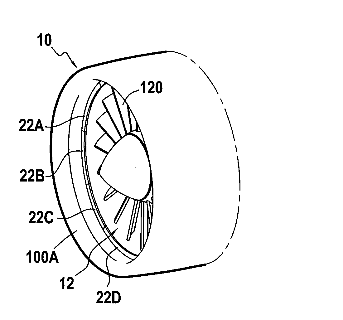
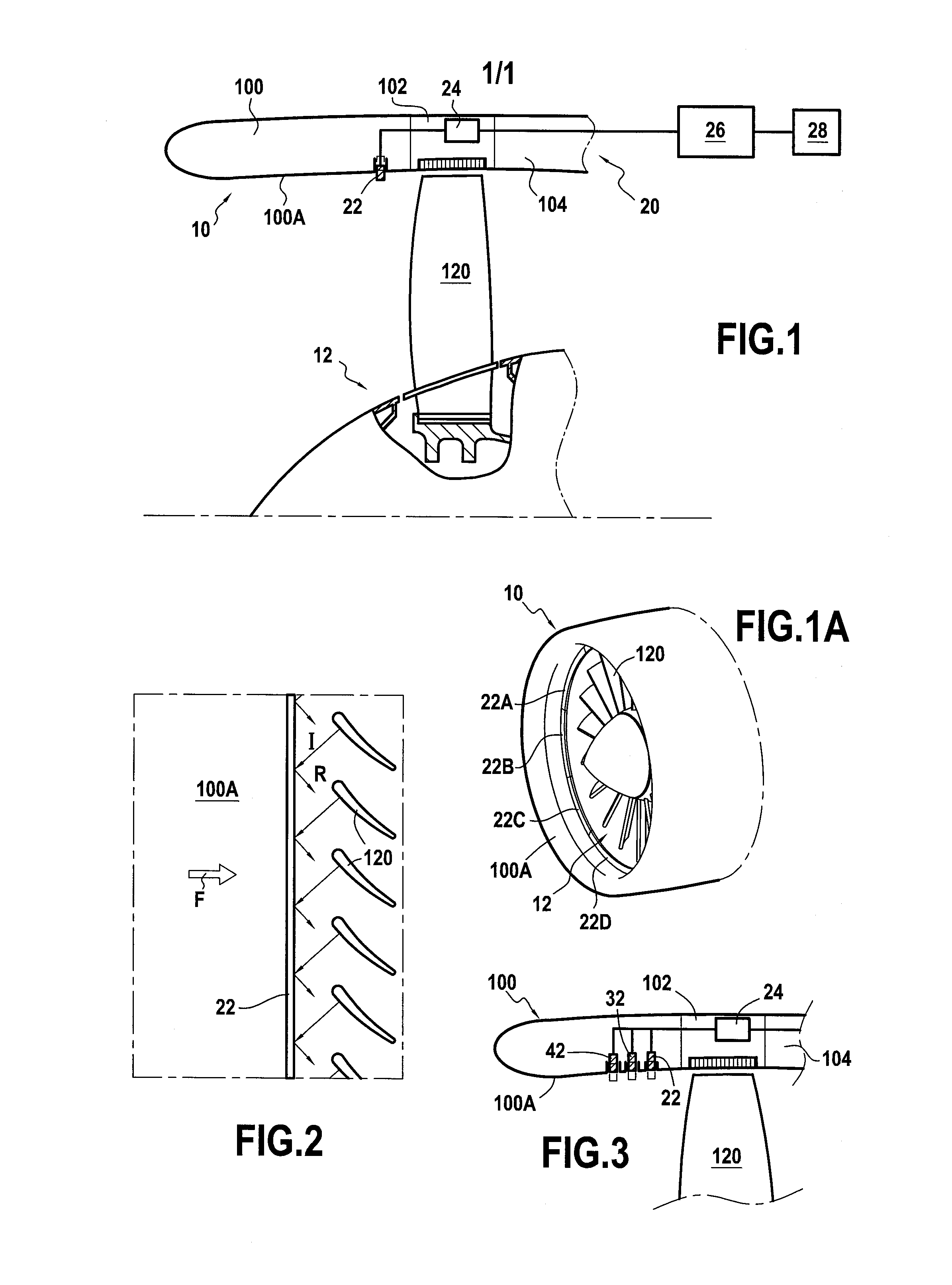
[0026]FIG. 1 is a fragmentary longitudinal half-section view of a nacelle 10 surrounding a fan 12 of a turbine engine power plant, e.g. an airplane turbojet. Conventionally, the nacelle comprises in the direction of the air stream passing therethrough (from left to right in FIG. 1 and referenced F in FIG. 2): a front annular portion or air inlet 100; an intermediate annular portion or fan casing 102; and a rear annular portion 104. The nacelle is generally secured to the structure of the airplane by means of a mast or pylon (not shown).

[0027]The air inlet and more particularly its inside surface 100A forming an air feed channel is shaped to ensure turbulence-free flow under various flying conditions: takeoff, cruising, and landing, starting from its leading edge and going up to the blades of the fan.

[0028]At present, interchanges between mechanical, aerodynamic, and acoustic engineers while designing fan blades are becoming more and more complex, given the high stakes and the ambiti...


PUM


Abstract

A nacelle structure (10) surrounding a fan, the structure comprising an air inlet (100) having an inside surface (100A) defining an air feed channel; and at least one ring (22) arranged in the air inlet and selectively movable between a deployed position in which the ring is moved radially inwards from the inside surface to provide an obstacle to shock waves coming from the fan, and a retracted position in which the ring is moved radially outwards from the deployed position so as to become flush with the inside surface and thus reconstitute the air feed channel.

Description

BACKGROUND OF THE INVENTION[0001]The present invention relates to the field of aviation, and more particularly to the air inlets of nacelles of turbine engines, i.e. airplane turboprops and turbojets.[0002]In conventional manner, airplane engines are housed in nacelles situated at various locations on an airplane, in or under a wing, or indeed on the rear fuselage, for example, where such a nacelle has an air inlet oriented along its axis, with a generally annular leading edge at the front, and presenting a streamlined profile for guiding the air sucked in by the engine.[0003]The sounds emitted by such engines originate mainly from the jet leaving the nozzle and also from the noise of the fan resulting from its blades rotating and moving past the fan casing.[0004]At transonic speeds, where Mach numbers for the flow over the blades are locally greater than 1, shock waves form at the leading edges of the blades and propagate along spiral paths upstream from the inlet with decreasing a...

Claims


Application Information

Patent Timeline
IPC IPC(8): F02C7/045
CPCF02C7/045F02K3/062F02C7/057B64D2033/0206B64D2033/0226F05D2260/962B64D33/02
Inventor ROMANO, PASCALBONNEAU, VIRGINIESENSIAU, CLAUDE
Owner SN DETUDE & DE CONSTR DE MOTEURS DAVIATION S N E C M A
Why Eureka
Eureka Blog
Learn More