Air-conditioning system

Active Publication Date: 2015-12-17
MITSUBISHI ELECTRIC CORP
View PDF10 Cites 14 Cited by
  • Summary
  • Abstract
  • Description
  • Claims
  • Application Information

AI Technical Summary

Benefits of technology

[0012]The air-conditioning system according to the present invention can control the evaporating temperature in accordance with an outdoor air load determined on the basis of the temperature and humid

Problems solved by technology

A high enthalpy of air introduced from outdoor air during cooling causes a cooling load (outdoor air load).
In such an operation of processing the latent heat load while the evaporating temperature is kept at a constant low temperature, however, operation efficiency (energy efficiency) is reduced beca

Method used


Image

  • Air-conditioning system
  • Air-conditioning system
  • Air-conditioning system

Examples


embodiment

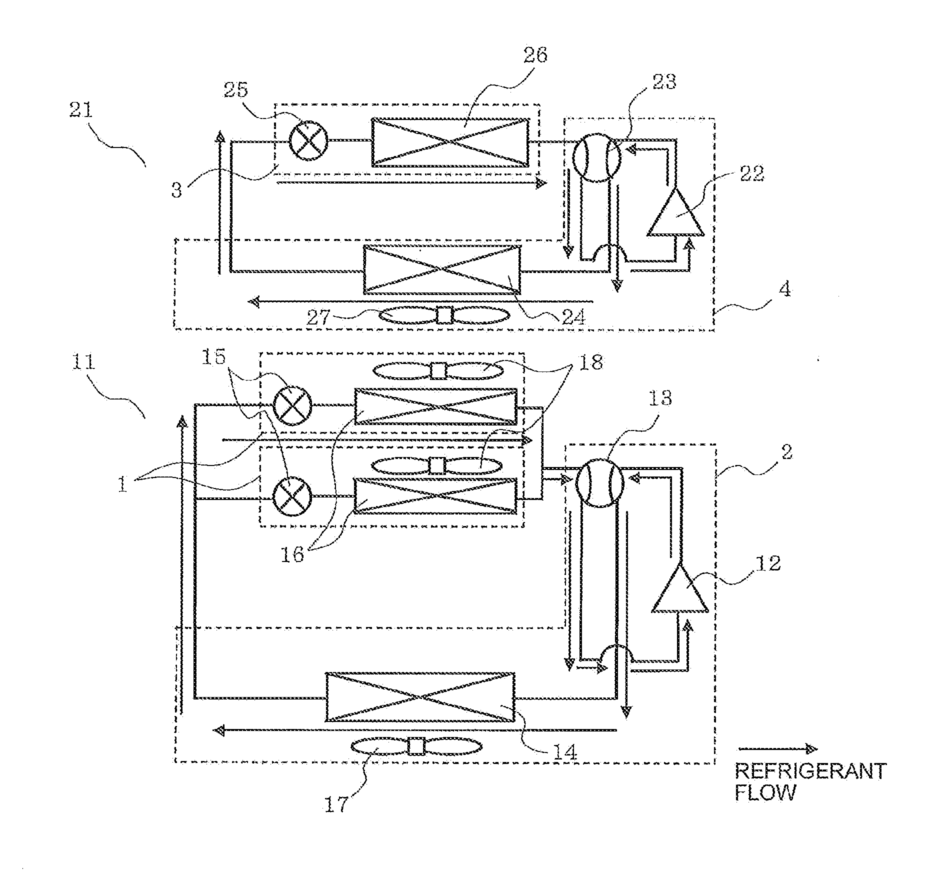
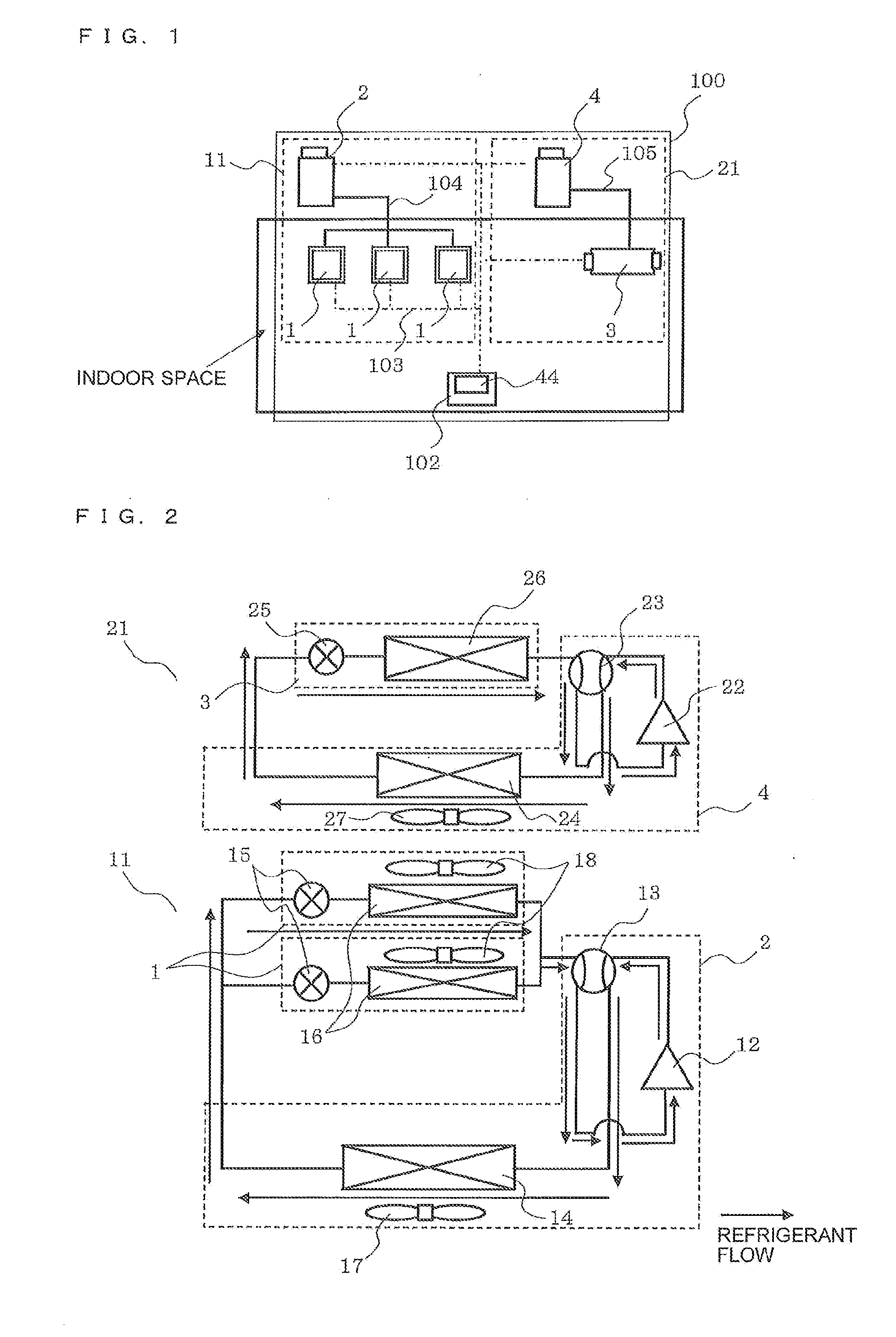
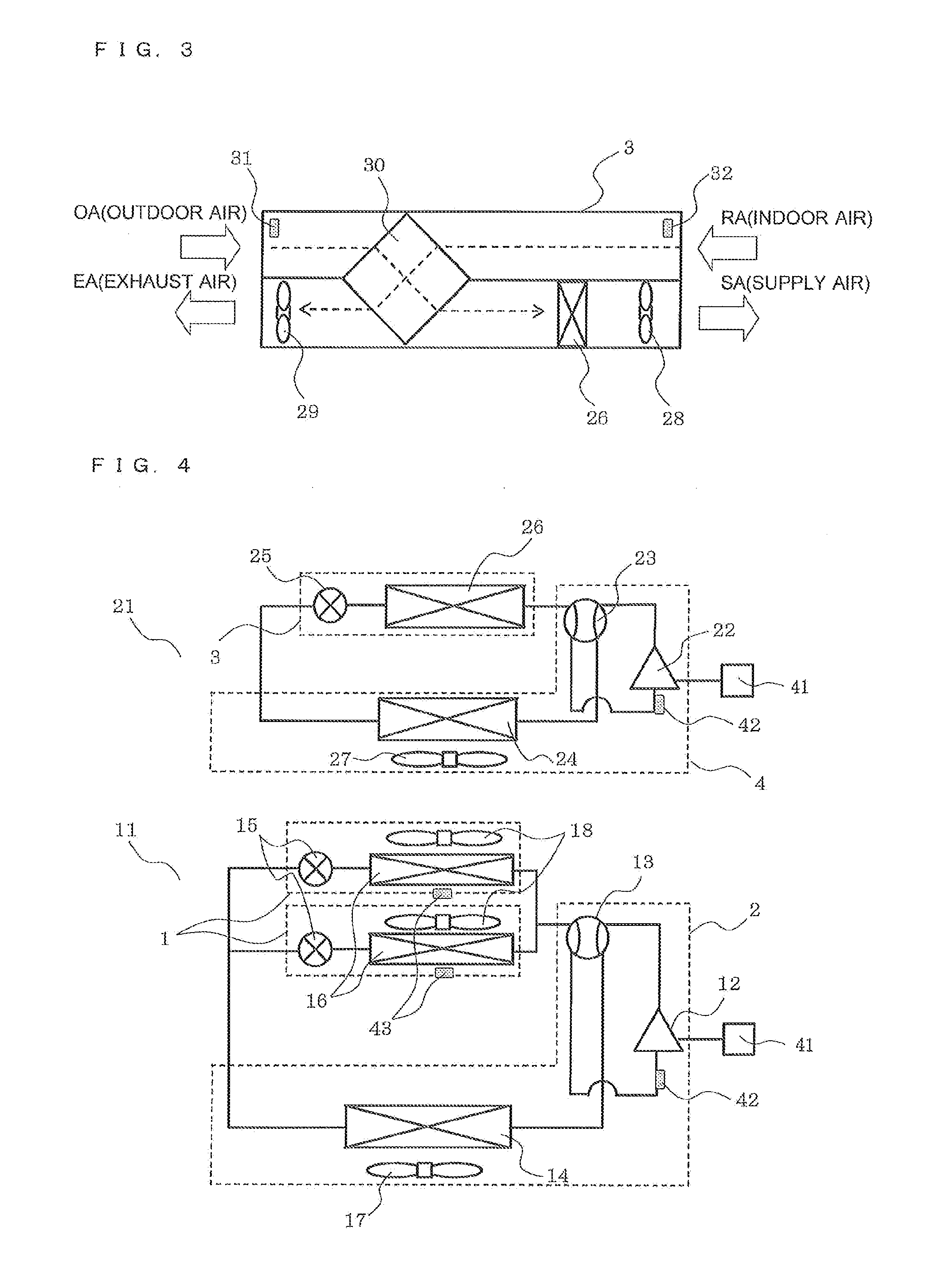
[0028]FIG. 1 is a schematic diagram of an air-conditioning system according to Embodiment of the present invention. FIG. 2 is a refrigerant circuit diagram 1 of the air-conditioning system according to Embodiment of the present invention.

[0029]The configuration of an air-conditioning system 100 will now be described.

[0030]The air-conditioning system 100 is installed in a building, a condominium, or other constraints, and is capable of processing a cooling load or a heating load by using a refrigerant circuit through which refrigerant is circulated. The air-conditioning system 100 includes two refrigerant circuits, an indoor unit circuit 11 (first refrigerant circuit) and a ventilator circuit 21 (second refrigerant circuit). These circuits are connected to a central controller 102 by transmission lines 103. The central controller 102 includes a target temperature and humidity setting unit 44. The central controller 102 controls the air-conditioning system 100.

[0031]In the indoor unit...


PUM


Abstract

An air-conditioning system is configured to determine an evaporating temperature control range of a first refrigerant circuit on the basis of the temperature of outdoor air, control an evaporating temperature of the first refrigerant circuit to a target evaporating temperature determined within the evaporating temperature control range of the first refrigerant circuit, determine an evaporating temperature control range of a second refrigerant circuit on the basis of the humidity of the outdoor air, and control an evaporating temperature of the second refrigerant circuit to a target evaporating temperature determined within the evaporating temperature control range of the second refrigerant circuit.

Description

TECHNICAL FIELD[0001]The present invention relates to an air-conditioning system including a ventilator.BACKGROUND ART[0002]A related-art air-conditioning system including a ventilator includes a refrigerant circuit including a compressor, a four-way valve, an outdoor heat exchanger, an expansion unit, and an indoor heat exchanger. The refrigerant circuit is filled with refrigerant. During cooling, the refrigerant is compressed into high-temperature high-pressure gas refrigerant by the compressor and is then delivered to the outdoor heat exchanger. The refrigerant which has flowed into the outdoor heat exchanger radiates heat to air and thus liquefies.[0003]The liquefied refrigerant is subjected to pressure reduction into a two-phase gas-liquid state by the expansion unit. In the indoor heat exchanger, the refrigerant removes heat from ambient air and thus gasifies. On the other hand, the air from which heat has been removed can cool an indoor space. The gasified refrigerant returns...

Claims


Application Information

Patent Timeline
IPC IPC(8): F24F5/00F25B7/00F24F1/0035F25B41/20F25B41/31
CPCF25B7/00F24F5/001F25B13/00F25B49/022F25B2313/0233F25B2400/061F25B2600/0253F25B2700/21151F24F3/065F24F2110/12F24F2110/22F24F2140/20F24F11/83F24F1/0035Y02B30/70F24F11/84
Inventor HAMADA, MAMORUUNEZAKI, FUMITAKETAMURA, NAOMICHINISHIMIYA, KAZUNOBUARAI, HIDEMOTO
Owner MITSUBISHI ELECTRIC CORP
Why Eureka
Try Eureka