Powder-filling system
a technology of filling system and powder, which is applied in the direction of magnetic bodies, packaging goods types, manufacturing tools, etc., can solve the problem that the opening size of the sieve needs to be much greater
- Summary
- Abstract
- Description
- Claims
- Application Information
AI Technical Summary
Benefits of technology
Problems solved by technology
Method used
Image
Examples
embodiment
(1) Embodiment of Powder-Filling System
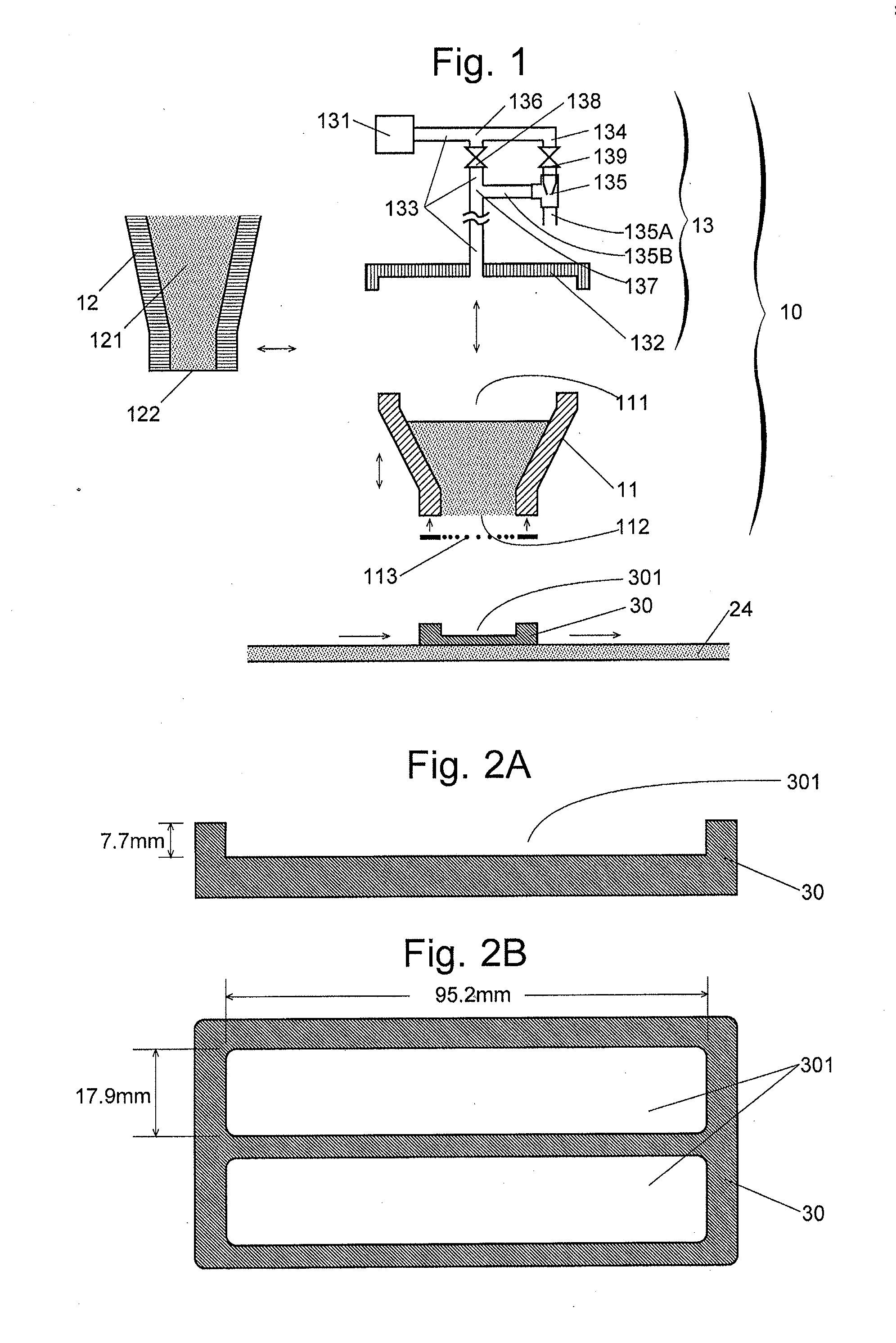
[0046]Initially, the powder-filling system 10 of the present embodiment is described. The powder-filling system 10 shown in FIG. 1 is intended to be used in a sintered magnet production system 20 of the present embodiment (which will be described later) to fill a container 30 with alloy powder to be used as the material of a sintered magnet, although it can also be used, without any change, to fill a container with any other type of powder. As shown in FIGS. 2A and 2B, the container 30 used in the present embodiment has two cavities 301 each of which has a roughly rectangular parallelepiped shape measuring 95.2 mm in length, 17.9 mm in width and 7.7 mm in depth and which are arranged side-by-side in their width direction.
(1-1) Configuration of Powder-Filling System 10
[0047]The powder-filling system 10 has a hopper 11, a powder supplier 12 for supplying alloy powder to the hopper 11, a gas supplier 13 for supplying compressed gas to the hopper 1...
first experiment
(3-1) First Experiment
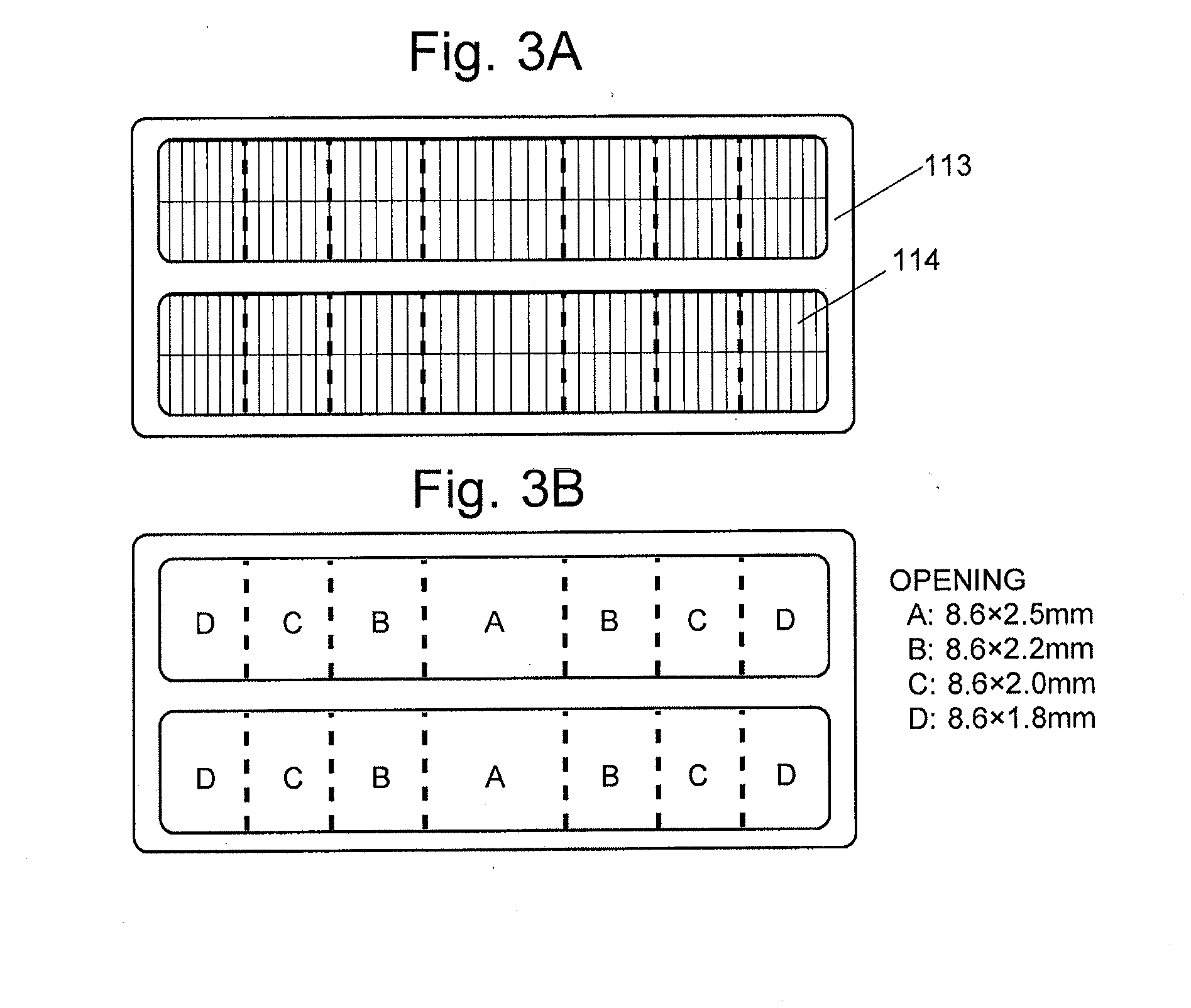
[0080]In the first experiment, a sintered magnet was produced using the sieve member 113 and the container 30 (Present Example 1). Another sintered magnet was also produced using a sieve member having the same size of openings (8.6×2.2 mm) across the entire grid instead of the sieve member 113, and the container 30 (Comparative Example 1). In both Present Example 1 and Comparative Example 1, the obtained sintered magnets approximately measured 80 mm×15 mm×5 mm and were slightly smaller than the cavity 301 due to shrinkage which occurs during the sintering process. The sintered magnets obtained in Present Example 1 and Comparative Example 1 were each equally divided into six pieces along the length direction. Thus, six sintered-magnet pieces were obtained for each (FIG. 8A). For each of these sintered-magnet pieces, the residual magnetic flux density Br was measured. The result is shown in FIG. 8B.
[0081]In Comparative Example 1, the sintered-magnet pieces near t...
second experiment
(3-2) Second Experiment
[0084]In the second experiment, a sintered magnet was produced using the sieve member 1131 and the container 30A (Present Example 2). Another sintered magnet was also produced using a sieve member having the same size of openings (8.0×2.0 mm) across the entire sieve instead of the sieve member 1131, and the container 30A (Comparative Example 2). In both Present Example 2 and Comparative Example 2, twelve pieces of sintered magnets were obtained from the alloy powder placed in the twelve cavities of the container 30A. FIG. 9 shows the measured result of the residual magnetic flux density Br for each sintered magnet.
[0085]In Comparative Example 2, the distribution of the residual magnetic flux density Br was such that the sintered magnets produced from the alloy powder placed in the cavities corresponding to sieves A (FIG. 5C) had the highest residual magnetic flux densities Br, followed by sieves B, C (no difference could be recognized between B and C at the pr...
PUM
| Property | Measurement | Unit |
|---|---|---|
| width | aaaaa | aaaaa |
| length | aaaaa | aaaaa |
| length | aaaaa | aaaaa |
Abstract
Description
Claims
Application Information
 - R&D
- Intellectual Property
- Life Sciences
- Materials
- Tech Scout
- Unparalleled Data Quality
- Higher Quality Content
- 60% Fewer Hallucinations
Browse by: Latest US Patents, China's latest patents, Technical Efficacy Thesaurus, Application Domain, Technology Topic, Popular Technical Reports.
© 2025 PatSnap. All rights reserved.Legal|Privacy policy|Modern Slavery Act Transparency Statement|Sitemap|About US| Contact US: help@patsnap.com


