
Apparatus and method for frequency-domain thermo-acoustic tomographic imaging

Inactive Publication Date: 2015-12-24
HELMHOLTZ ZENT MUNCHEN DEUTES FORSCHUNGSZENT FUR GESUNDHEIT & UMWELT
View PDF0 Cites 22 Cited by
  • Summary
  • Abstract
  • Description
  • Claims
  • Application Information

AI Technical Summary

Benefits of technology

The invention is a new tomographic approach for optoacustic and thermo-acoustic imaging that improves image quality by measuring over different angular projections. Unlike conventional methods, it is based on excitation with a continuously operating source device, avoiding the need for complex pulse sources. This makes it cost-efficient and easier to apply in sensitive objects. The use of mathematical methods for image formation, specifically mathematical inversion, can further improve image performance by incorporating features of the hardware employed in image formation. Overall, the invention has the potential to offer better tomographic images using simple and cost-efficient methods.

Problems solved by technology

Nevertheless, the TD tomographic approaches have limitations in terms of complex pulse sources, measurement speed and high peak intensities of excitation pulses operating at low duty cycles.
Similar to U.S. Pat. No. 4,255,971, the system performance was limited to 2D surface scanning of tissues.
Imaging performance of this frequency domain optoacoustic imaging scanner was comparably limited to lateral (x y) scans of tissue and did not yield tomographic views of targets.
Furthermore, the conventional three-dimensional optoacoustic imaging has disadvantages in terms of limited view scanning of targets, low imaging velocity, low spatial resolution and low SNR.

Method used


Image

  • Apparatus and method for frequency-domain thermo-acoustic tomographic imaging
  • Apparatus and method for frequency-domain thermo-acoustic tomographic imaging
  • Apparatus and method for frequency-domain thermo-acoustic tomographic imaging

Examples


Embodiment Construction

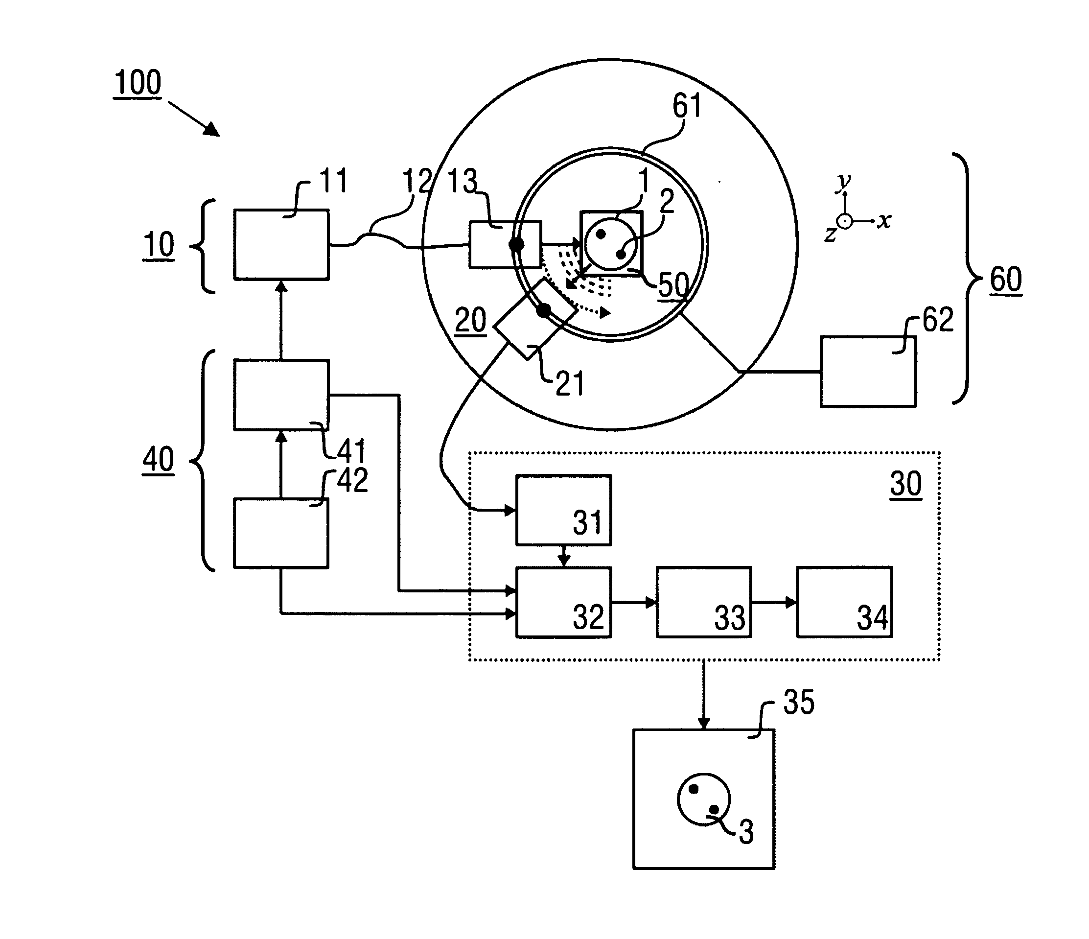
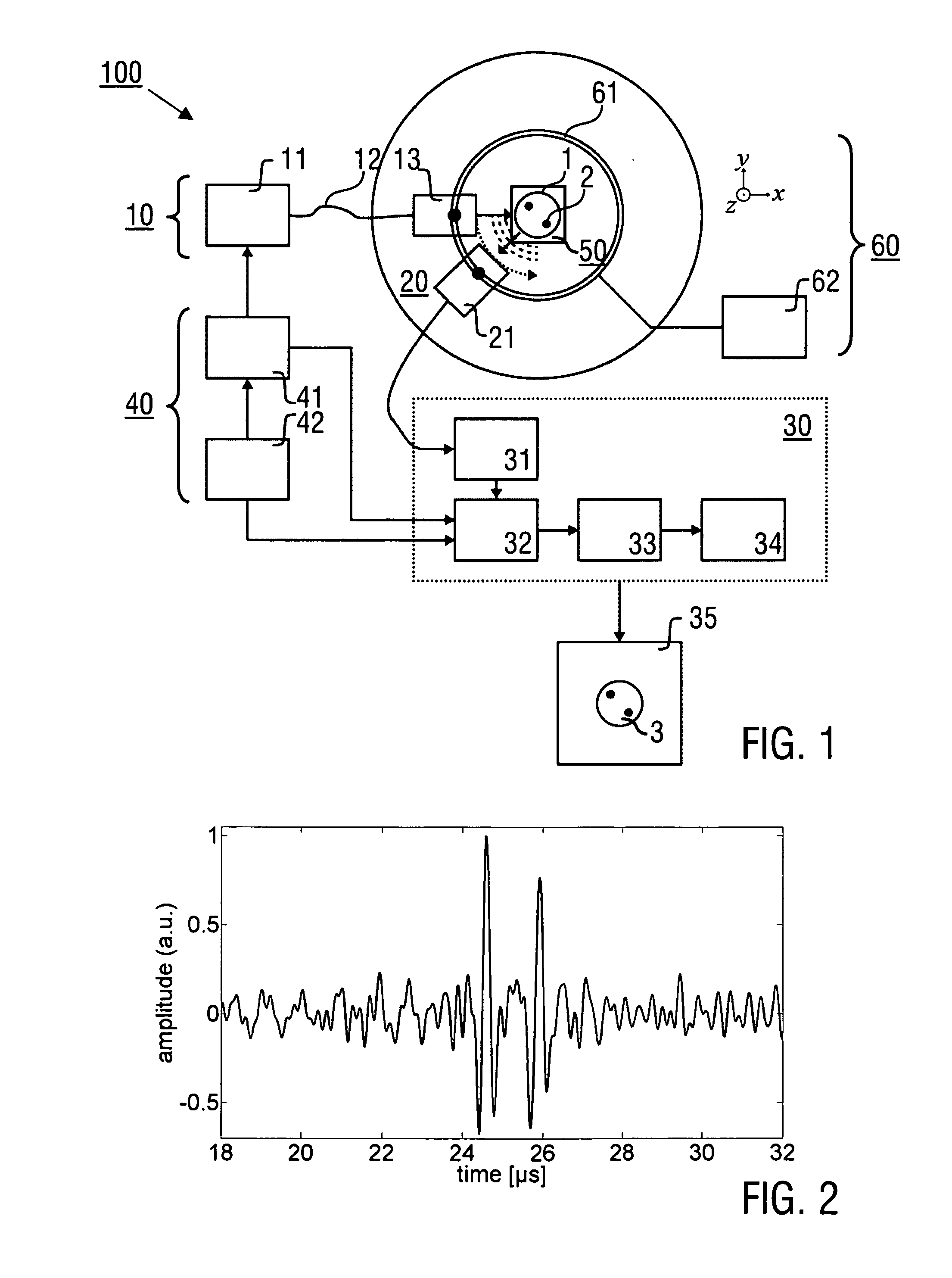
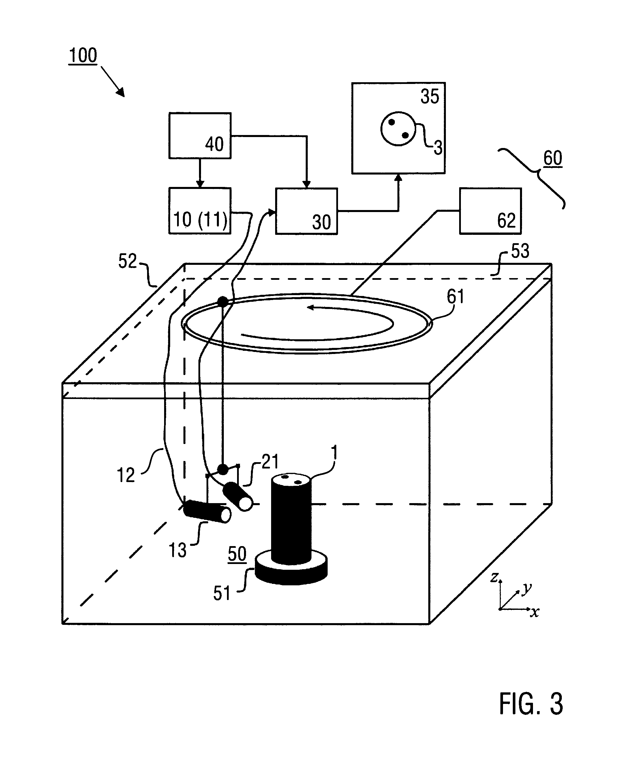
[0050]Preferred features of the imaging apparatus and method for thermo-acoustic tomographic imaging according to the invention are described in the following with particular reference to the mathematical basics of the thermo-acoustic signal generation and image data reconstruction (1.), embodiments of the imaging apparatus (2.), preferred applications (3.) and experimental results (4.). Exemplary reference is made to the imaging of biological tissue. It is emphasized that the implementation of the invention is not restricted to the illustrated examples but rather possible in particular with modified arrangements of the imaging apparatus, further applications and other objects, like e. g. workpieces. In particular, the illustrated arrangements can be replaced by modified designs, wherein at least one detector element or detector array of the detector device and at least one emitter or an emitter array of the source device are arranged in a hand held unit.

1. Thermo-Acoustic Signal Ge...


PUM


Abstract

An imaging apparatus (100), configured for thermoacoustic tomographic imaging a region of interest (2) in an object (1), comprises a source device (10) being arranged for emitting an electromagnetic energy input into the region of interest (2), a detector device (20) being arranged for detecting mechanical wave response signals generated in the region of interest (2) along multiple angular projection directions in response to the electromagnetic energy input, and an image data acquisition and processing device (30) being arranged for providing tomographic image data representing the image of the region of interest (2) on the basis of the mechanical wave response signals, wherein the source device (10) is adapted for continuously emitting the electromagnetic energy input with a predetermined input modulation, and the image data acquisition and processing device (30) is adapted for converting the mechanical wave response signals into the frequency domain and for performing data processing and image reconstruction in the frequency domain or in the time domain. Furthermore, an imaging method for thermoacoustic tomographic imaging a region of interest (2) in an object (1) is described.

Description

TECHNICAL FIELD[0001]The present invention relates to an imaging apparatus and an imaging method for thermoacoustic (including opto-acoustic and photoacoustic) tomographic imaging a region of interest in an object. In particular, the inventive technique is capable of generating cross-sectional images of biological tissue through detection of electromagnetic absorption across the electromagnetic spectrum.TECHNICAL BACKGROUND OF THE INVENTION[0002]Thermo-acoustic imaging relies on the absorption of electromagnetic energy by tissue and the corresponding tissue heating, resulting in acoustic pressure release because of thermoelastic expansion of the tissue. While the term thermo-acoustic imaging is employed to determine generally any form of energy absorption by tissue, the terms optoacoustic or photo-acoustic more specifically reflect imaging when the energy employed is light. Based on this physical phenomenon, optoacoustic imaging (OAI) and thermo-acoustic imaging (TAI) techniques, or...

Claims


Application Information

Patent Timeline
IPC IPC(8): A61B5/00A61B19/00G01N21/17
CPCA61B5/0095G01N21/1702A61B19/54G01N2201/12G01N2021/1706G01N2201/06113G01N2201/08A61B5/6852A61B2503/40A61B2503/42A61B2560/0406A61B2562/14A61B2562/143A61B90/39G01N29/2418G01N2291/02466G01N2291/02475
Inventor KELLNBERGER, STEPHANNTZIACHRISTOS, VASILISSERGIADIS, GEORGEDELIOLANIS, NIKOLAOSOMAR, MURAD
Owner HELMHOLTZ ZENT MUNCHEN DEUTES FORSCHUNGSZENT FUR GESUNDHEIT & UMWELT
Learn More