Turbo machine combustion assembly comprising an improved fuel supply circuit

Inactive Publication Date: 2015-12-24
SAFRAN HELICOPTER ENGINES
View PDF18 Cites 8 Cited by
  • Summary
  • Abstract
  • Description
  • Claims
  • Application Information

AI Technical Summary

Benefits of technology

[0019]The supply circuit is therefore a complex assembly with a h

Problems solved by technology

During this step, the supply of fuel to the starting injectors stops and they are drained to avoid coking, which could cause them to

Method used


Image

  • Turbo machine combustion assembly comprising an improved fuel supply circuit
  • Turbo machine combustion assembly comprising an improved fuel supply circuit
  • Turbo machine combustion assembly comprising an improved fuel supply circuit

Examples


first embodiment

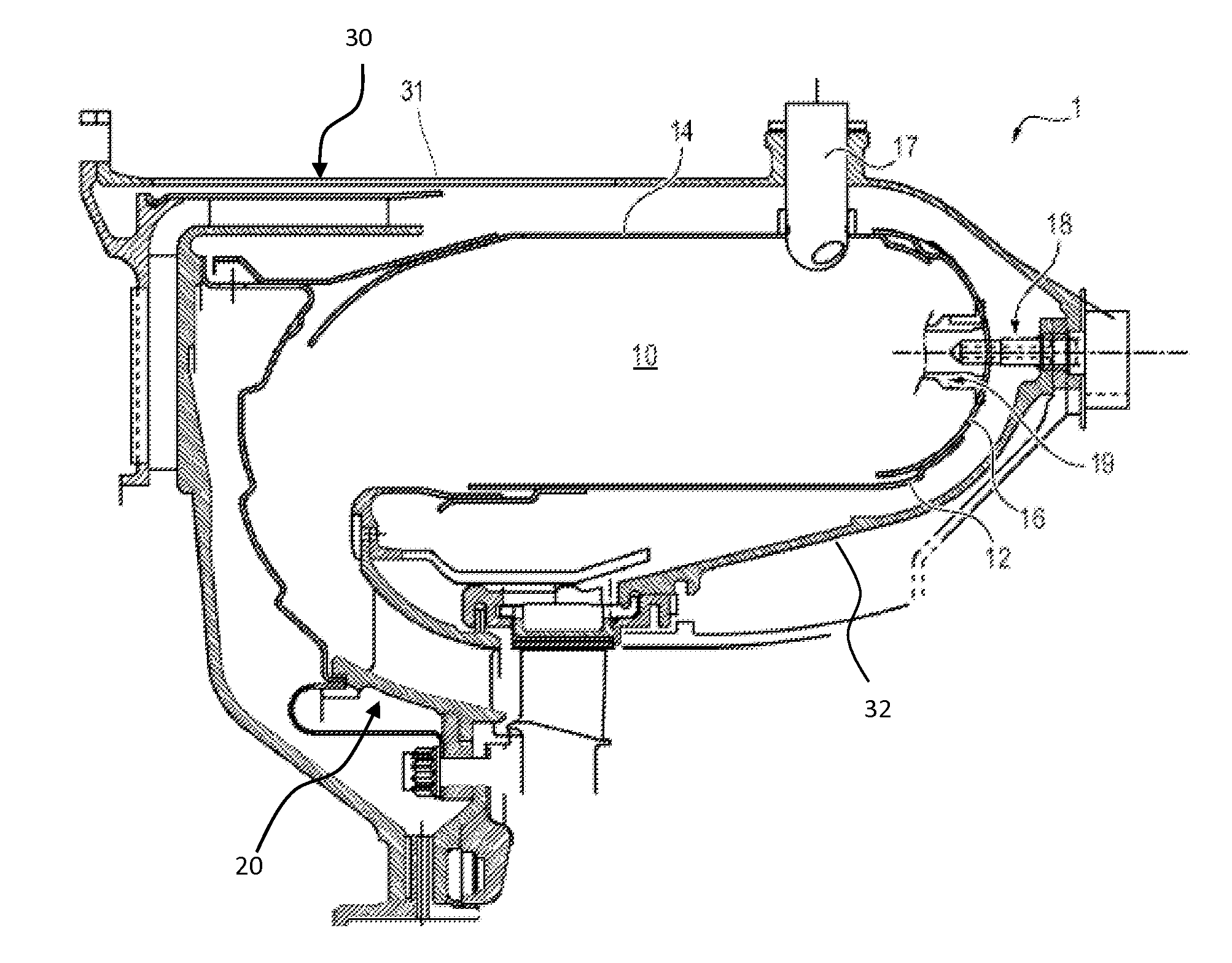
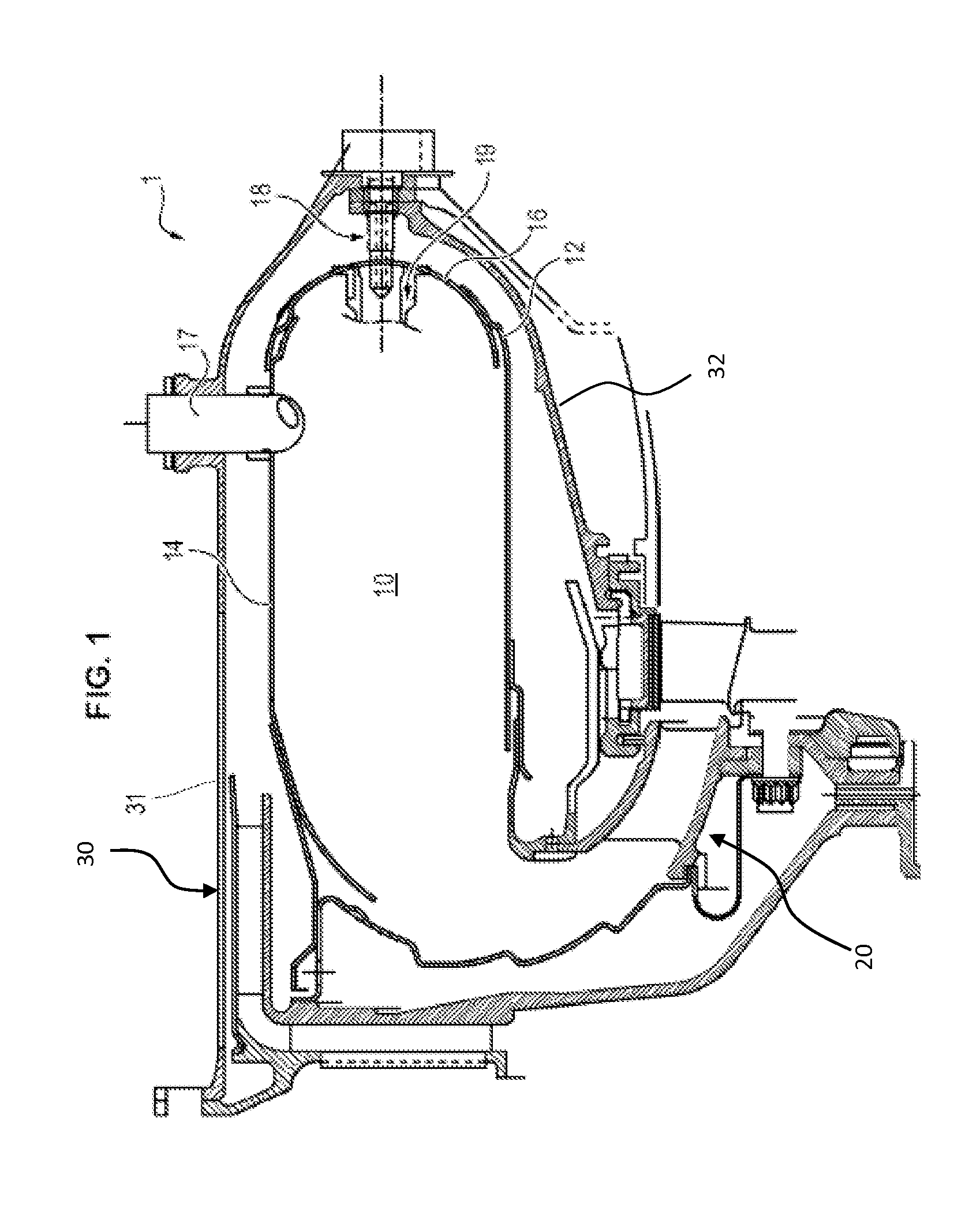
[0056]According to the turbomachine, represented in FIG. 3a, the combustion chamber is of the preevaporation rod type, wherein each main injector 18 opens into a preevaporation rod 19, itself opening inside the chamber. Each pre-evaporation rod comprises a duct opening via two openings into the combustion chamber.

[0057]The pre-evaporation rods 19 enter the combustion chamber through an opening formed in the outer wall 14 or in the chamber end wall 16 of the combustion chamber 10, and having a Tshaped section, the ends of which are curved toward the chamber end wall.

second embodiment

[0058]According to the turbomachine, represented in FIG. 3b, the main injectors 18 are of aerodynamic or aeromechanical type, and directly enter the chamber 10 through an opening formed in the chamber end wall 16.

[0059]Advantageously, the combustion chamber is of reverse flow type.

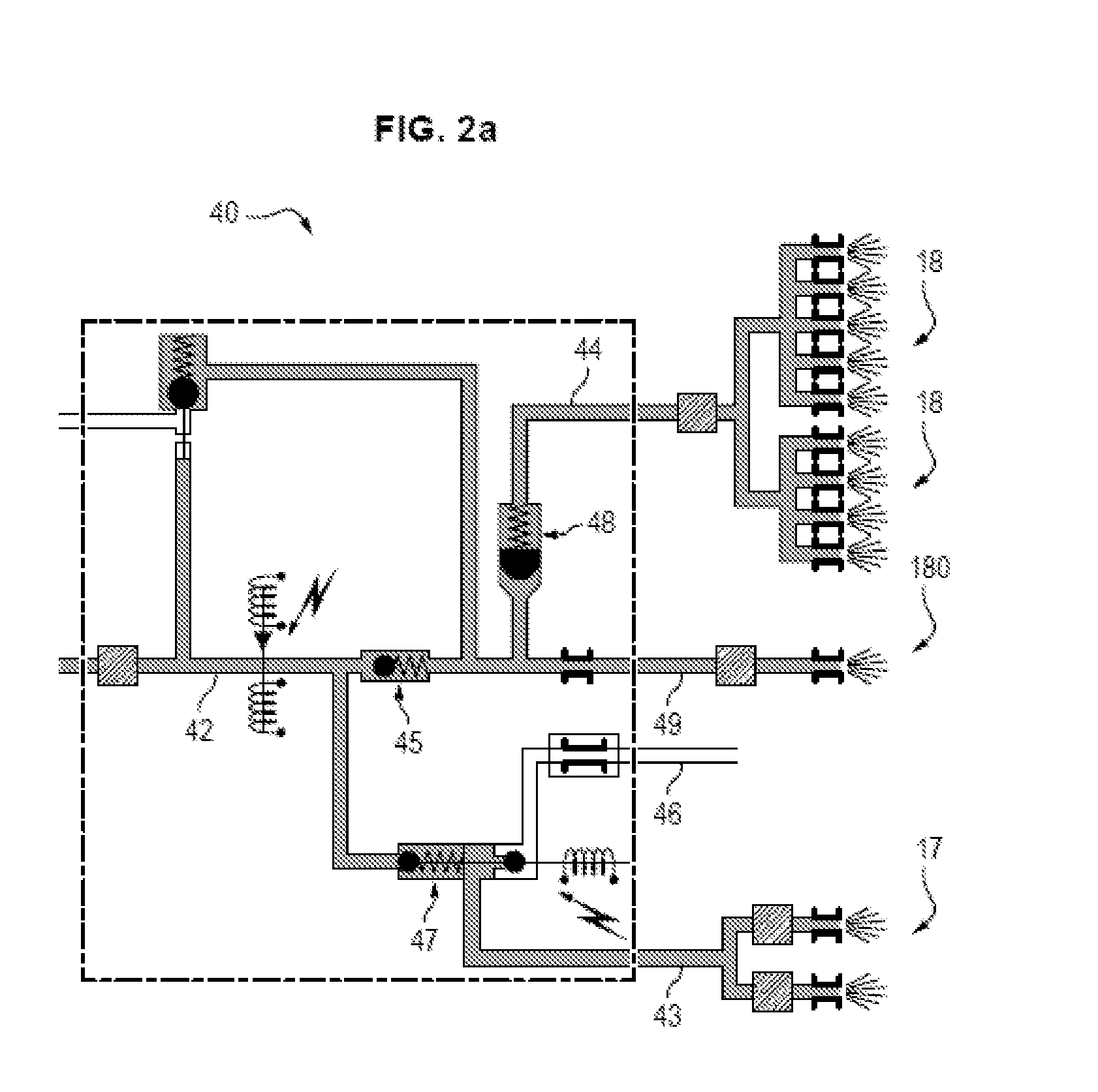
[0060]The turbomachine 1 also comprises a fuel supply circuit 40 for the injectors, said circuit being represented in FIG. 4.

[0061]The fuel supply circuit comprises a fuel injection inlet 41, by which the fuel enters the circuit along a fuel distribution duct 42.

[0062]The fuel distribution duct is connected to the starting injectors by a supply duct 43 for the starting injectors, and to the main injectors by a supply duct 44 for the main injectors.

[0063]The fuel supply circuit is designed to supply fuel to the starting injectors continuously, so that said injectors are supplied with fuel both during a step of initiating the combustion in which the fuel is set alight by the spark plug, and during the later ...


PUM


Abstract

Turbo machine combustion assembly (1) comprising a combustion chamber (10), at least one starting injector (17), a plurality of main injectors (18) distributed at constant angular intervals around the circumference of the combustion chamber, each starting injector being positioned between two consecutive main injectors, equal distances therefrom, and a fuel supply circuit (40) supplying fuel to the injectors, in which assembly the combustion chamber is delimited by two axisymmetric walls—an external wall (14) and an internal wall (12)—which are connected by an annular chamber end wall (16), the fuel supply circuit being designed to supply at least one starting injector continuously, each continuously-supplied starting injector being oriented toward the chamber end wall and dimensioned to spread a spray (F) of fuel between 120° and 180° wide, and the flow rate of fuel injected by the main injectors (18′) between which the starting injectors are positioned being reduced by comparison with the flow rate injected by the other main injectors (18).

Description

FIELD OF THE INVENTION[0001]The invention relates to the field of turbomachines, and more specifically the field of turbomachine combustion assemblies, comprising a combustion chamber and a plurality of injectors dedicated to starting and supplying fuel to the combustion chamber.PRIOR ART[0002]With reference to FIG. 1, turbomachines 1 conventionally include a combustion chamber 10 and a distributor 20 housed in a casing 30, the combustion chamber being delimited by axisymmetric outer 14 and inner 12 walls extending one inside the other and which are connected by an annular chamber end wall 16.[0003]The casing also has an inner wall 32 and an outer wall 31 to which the inner 12 and outer 14 walls of the combustion chamber are respectively fastened.[0004]A mixture of air and fuel is injected into the combustion chamber by a plurality of injectors, this mixture being combusted to generate the energy needed to propel the turbomachine.[0005]Several types of injectors are positioned in a ...

Claims


Application Information

Patent Timeline
IPC IPC(8): F23R3/34F23R3/42
CPCF23R3/42F23R3/34F02C7/228F02C9/34F23R3/343F23R3/32F23R3/50
Inventor BADET, JEAN-PIERREVERDIER, HUBERT PASCAL
Owner SAFRAN HELICOPTER ENGINES
Why Eureka
Try Eureka