Capacitive sensor, acoustic sensor and microphone

a technology of capacitive sensor and acoustic sensor, which is applied in the direction of instruments, specific gravity measurement, furnaces, etc., can solve problems such as obstructing factors, and achieve the effect of reducing sensor size and improving sensitivity

Active Publication Date: 2015-12-24
MMI SEMICON CO LTD
View PDF8 Cites 30 Cited by
  • Summary
  • Abstract
  • Description
  • Claims
  • Application Information

AI Technical Summary

Benefits of technology

[0007]An object of the present invention is to provide a capacitive sensor such as an acoustic

Problems solved by technology

For this reason, the area of the substrate is larger than the area of the diaphragm,

Method used


Image

  • Capacitive sensor, acoustic sensor and microphone
  • Capacitive sensor, acoustic sensor and microphone
  • Capacitive sensor, acoustic sensor and microphone

Examples


embodiment 1

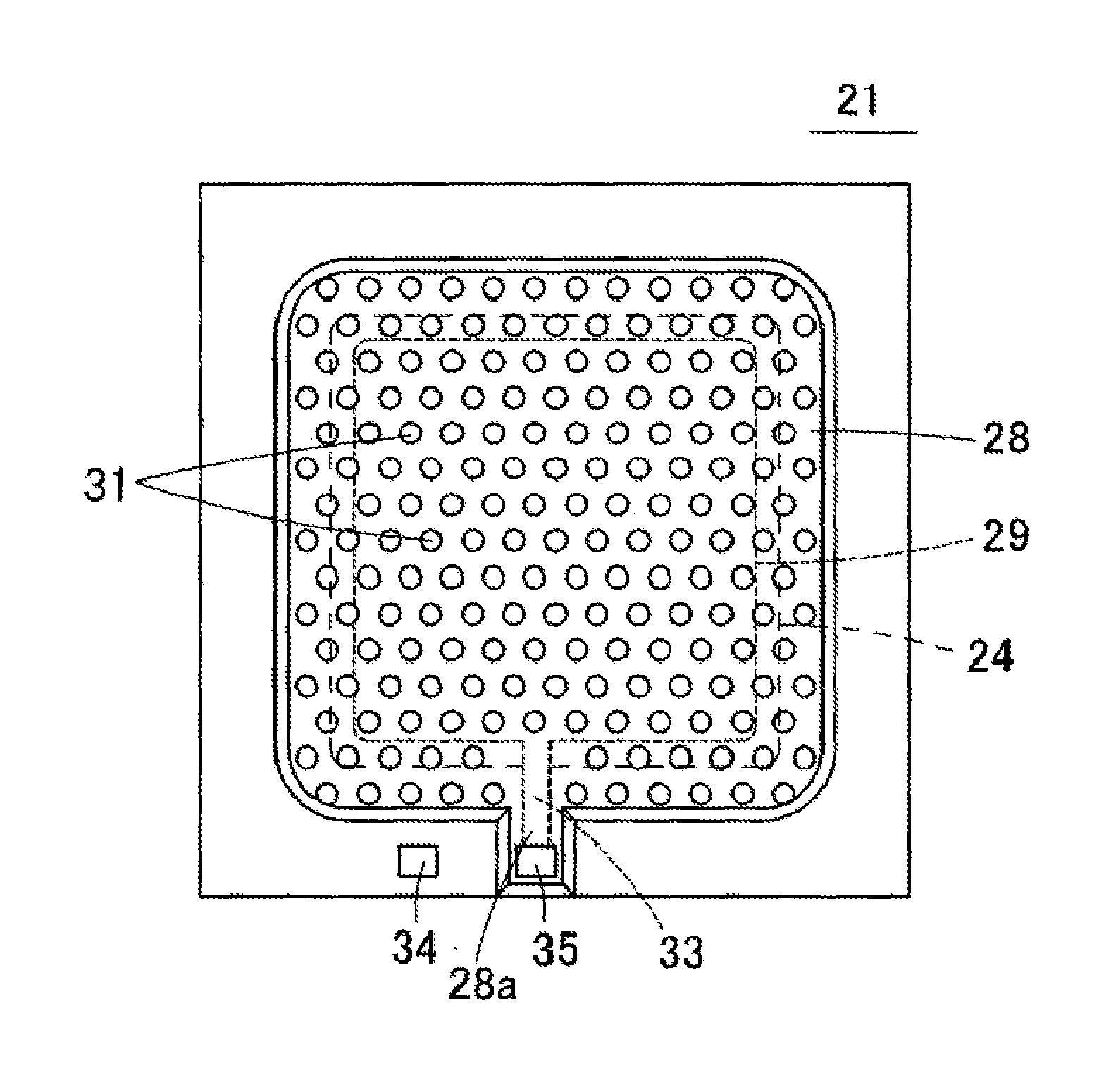
[0038]Hereinafter, a capacitive sensor according to Embodiment 1 of the present invention, that is to say an acoustic sensor 21, will be described with reference to FIGS. 3A, 3B, 4A, 4B and 5. FIG. 3(A) is a plan view showing the acoustic sensor 21 according to Embodiment 1 of the present invention. FIG. 3(B) is a plan view showing the acoustic sensor 21 in FIG. 3(A), in a state in which a back plate 28 and a fixed electrode plate 29 have been removed to expose a diaphragm 24. FIG. 4(A) is a cross-sectional diagram of the acoustic sensor 21. FIG. 4(B) is an enlarged view of the cross-section of a portion X in FIG. 4(A). FIG. 5 is a cross-sectional diagram showing a state in which the diaphragm 24 has undergone displacement.

[0039]This acoustic sensor 21 is a capacitive element that may be manufactured using MEMS technology. As shown in FIG. 4(A), this acoustic sensor 21 includes a diaphragm 24 provided on the upper surface of a silicon substrate 22 (substrate) via anchors 27, and a f...

modified example

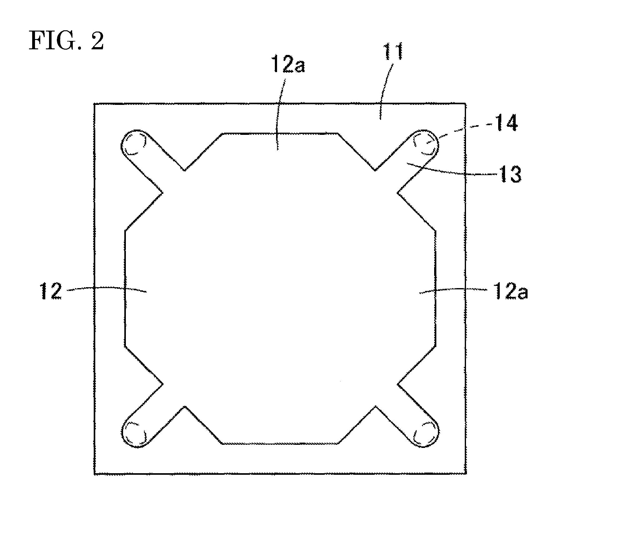
[0053]FIG. 6 shows a chamber 23 having a different planar shape as a modified example of Embodiment 1. In this modified example, the chamber 23 has an approximately octagonal shape in a view from above, and the chamber 23 extends into the regions between one leg piece 26 and another leg piece 26. With the chamber 23 having this shape as well, it is possible to increase the volume of the chamber 23 and reduce the length of the vent hole.

[0054]Also, the shape of the diaphragm 24 is not limited to the approximately rectangular shape shown in FIG. 3(B). For example, an octagonal diaphragm 24 as shown in FIG. 7(A) may be used, or a circular diaphragm 24 as shown in FIG. 7(B) may be used. Also, the number of and arrangement of the leg pieces 26 can also be appropriately changed in accordance with the shape of the diaphragm 24.

embodiment 2

[0055]FIG. 8(A) is a plan view showing an acoustic sensor 41 according to Embodiment 2 of the present invention. FIG. 8(B) is a plan view showing the acoustic sensor 41 in FIG. 8(A), in a state in which the back plate 28 and the fixed electrode plate 29 have been removed to expose the diaphragm 24. FIG. 9 is a cross-sectional diagram showing a state in which the diaphragm 24 has undergone displacement.

[0056]In the acoustic sensor 41 according to Embodiment 2 of the present invention as well, the leg pieces 26 extend in the diagonal directions of the diaphragm 24, but the end portions of the leg pieces 26 located on the central side of the diaphragm 24 are connected to the diaphragm 24, and the end portions on the outer peripheral side of the diaphragm 24 are supported by the anchors 27. Accordingly, in Embodiment 2, the leg pieces 26 extend outward from the diaphragm 24. Other aspects are similar to those in the case of Embodiment 1, and therefore portions of the configuration that ...


PUM


Abstract

A chamber that penetrates vertically is formed in a silicon substrate. A diaphragm is arranged on the upper surface of the silicon substrate so as to cover the upper opening of the chamber. Leg pieces are provided in corner portions of the diaphragm, within the diaphragm. The diaphragm and the leg pieces are separated by slits, and the leg pieces extend in the diagonal directions of the diaphragm. The leg pieces are connected to the diaphragm at the ends on the outer peripheral side of the diaphragm, and the ends on the central side of the diaphragm are supported by anchors provided on the upper surface of the silicon substrate. A back plate is provided above the silicon substrate so as to cover the diaphragm, and a fixed electrode plate is provided on the lower surface of the back plate so as to oppose the diaphragm.

Description

TECHNICAL FIELD[0001]The present invention relates to a capacitive sensor, an acoustic sensor, and a microphone. Specifically, the present invention relates to a capacitive sensor constituted by a capacitor structure that is made up of a vibrating electrode plate (diaphragm) and a fixed electrode plate. The present invention also relates to an acoustic sensor (acoustic transducer) that converts acoustic vibration into an electrical signal and outputs it, and a microphone that uses the acoustic sensor.RELATED ART[0002]Among diaphragms used in acoustic sensors, there are diaphragms that are supported by leg pieces in order to increase the amount of displacement of the diaphragm caused by acoustic vibration and thus improve the sensitivity of the acoustic sensor. FIG. 1(A) is a plan view showing a conventional acoustic sensor. Note that the back plate and the fixed electrode plate have been removed to expose the diaphragm in FIG. 1(A).[0003]In the acoustic sensor shown in FIG. 1(A), a ...

Claims


Application Information

Patent Timeline
IPC IPC(8): G01H11/06H04R19/04
CPCH04R19/04G01H11/06H04R19/005H01L2224/48091H01L2224/48137H01L2924/15151H01L2924/16152H01L2924/00014
Inventor INOUE, TADASHI
Owner MMI SEMICON CO LTD
Why Eureka
Try Eureka