Device for measuring residual oil

a technology of residual oil and measuring device, which is applied in the direction of gyroscope/turn-sensitive device, speed measurement using gyroscopic effects, liquid/fluent solid measurement, etc., can solve the problems of metal oxide, exponential characteristic curve, and difficult to determine the offset point, so as to increase the service life and stability

Inactive Publication Date: 2015-12-24
BEKO TECHNOLOGIES GMBH
View PDF2 Cites 8 Cited by
  • Summary
  • Abstract
  • Description
  • Claims
  • Application Information

AI Technical Summary

Benefits of technology

[0034]Furthermore, a catalyst unit is provided according to the invention, which enables an offset stabilization of the PID sensor with zero air. According to the invention, the PID sensor is flushed with a catalyst gas flow (catalyzed measuring gas) whenever it is not used and turned off. Thus, the PID sensor is always kept clean, and the stability and service life is increased. Only just before the PID sensor is operated in parallel with the MOX sensor, voltage is applied to the PID sensor and its lamp is turned on. After a sufficient stabilization time, an automatic zero adjustment takes place. After this adjustment, the original gas flow is divided into a first and a secon

Problems solved by technology

However, metal oxide semiconductor gas sensors are disadvantageous in that they have an exponential characteristic curve, which is why their offset point is difficult to determine.
The measurement results are relatively hard to reproduce, and the sensors have high cross sensitivities to water vapor and inorganic gases.
However, what is disadvantageous in sensors of this kind is their low level of sensitivity, which is relevant particularly in the low-concentration range.
Also, the state of ageing cannot be determ

Method used


Image

  • Device for measuring residual oil
  • Device for measuring residual oil

Examples


Embodiment Construction

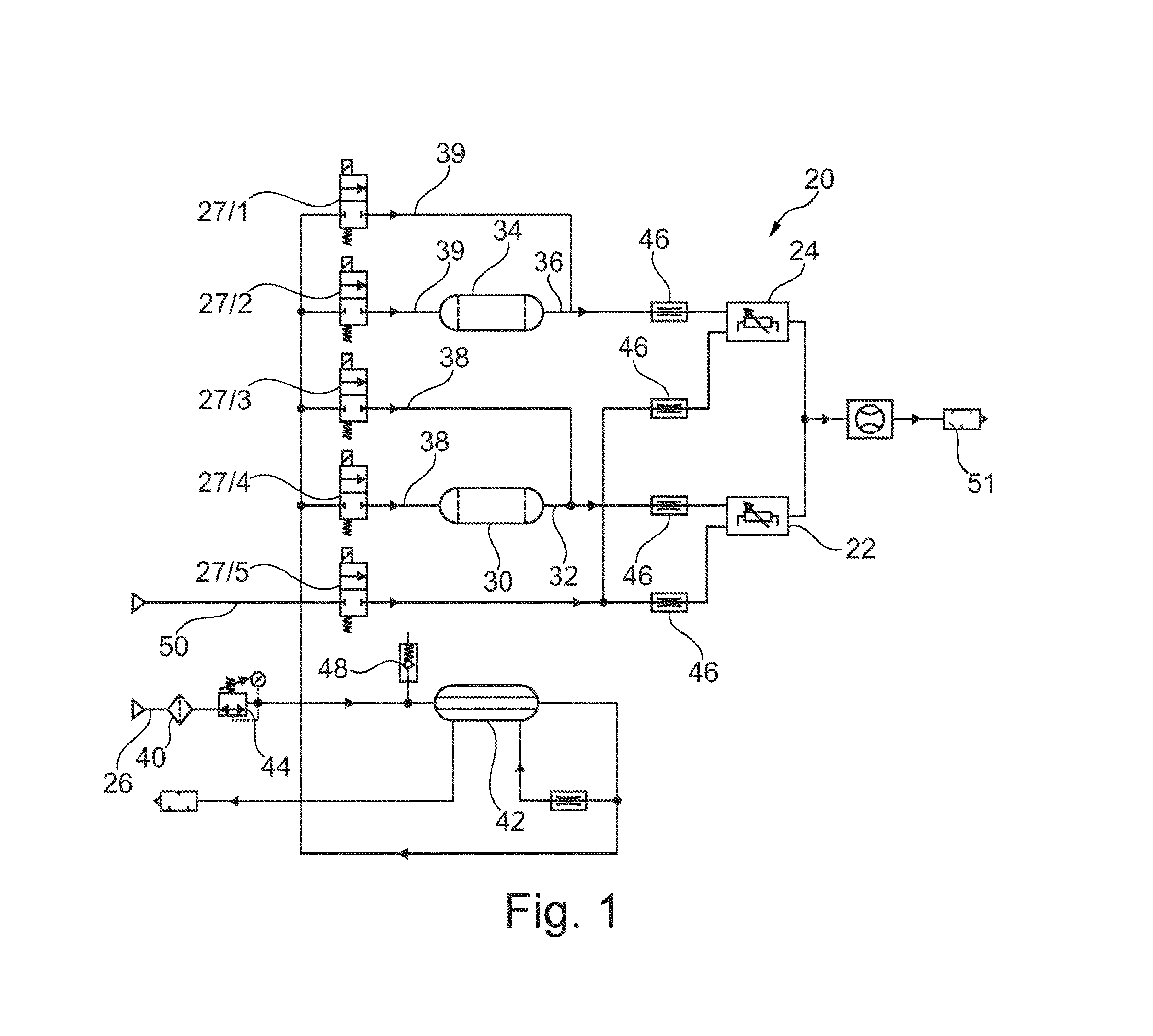
[0058]FIG. 1 shows a schematic diagram of the gas paths of the measuring device 20. It has two sensors, a metal oxide semiconductor gas sensor (hereinafter referred to as MOX sensor) as the first sensor 22, and a photoionization sensor (hereinafter referred to as PID sensor) as the second sensor 24.

[0059]An original gas flow 26 is divided into a first measuring gas flow 38 and a second measuring gas flow 39 via gas pipes and by means of valves 27.

[0060]In the exemplary embodiment shown, a catalyst unit 34, which generates a catalyst gas flow 36, is connected upstream from the second sensor 24. Analogously, a second catalyst unit 30, which generates a second catalyst gas flow 32, is connected upstream from the first sensor 22.

[0061]A filtering element 40 filtrates and a drying element 42 dries the original gas flow 26 and thus the two measuring gas flows 38, 39. The drying element 42 is preferably configured as a membrane dryer.

[0062]Moreover, a pressure regulator 44 and a safety val...


PUM


Abstract

The invention relates to a measuring device for detecting amounts of hydrocarbon in gases, and comprising—a first sensor (22) for determining the amount of hydrocarbon in a first measurement gas flow (38) and for producing a corresponding first measurement result,—a second sensor (24) for determining the amount of hydrocarbon in a second measurement gas flow (39) and for producing a corresponding second measurement result, and—an evaluation unit for evaluating the measurement results of the two sensors (22, 24),—the first sensor (22) being a metal oxide semiconductor gas sensor and carrying out measurements continuously, and—the second sensor (24) being a photoionisation sensor and carrying out measurements intermittently. (FIG. 1) The invention also relates to a method for recording the amount of hydrocarbon in a gas flow.

Description

TECHNICAL FIELD[0001]The present invention relates to a measuring device and a method for detecting the hydrocarbon content in gases.BACKGROUND[0002]Such measuring devices are known with various sensor technologies and serve for detecting the content of oil, hydrocarbons and oxidizable gases in, for example, air or compressed air.[0003]For example, electrically heatable metal oxide semiconductor gas sensors with semiconductor oxide materials are used frequently, which in the heated state change their electrical resistance depending on the amount of hydrocarbons contained in the air. The most important advantages of metal oxide semiconductor gas sensors include the very high sensitivity, and thus the possibility of being able to measure even the most minute hydrocarbon contents down to the ppt range. They have a very long operating life, a very good long-term stability, and the acquisition costs are rather low.[0004]However, metal oxide semiconductor gas sensors are disadvantageous i...

Claims


Application Information

Patent Timeline
IPC IPC(8): G01N33/00
CPCG01N33/0032Y10T436/218Y10T436/100833G01N33/0047G01N33/0006
Inventor FRIEDRICH, MARTIN
Owner BEKO TECHNOLOGIES GMBH
Why Eureka
Try Eureka