
Fluid dispensing control systems and methods

a control system and fluid technology, applied in the field of fluid control systems and methods, can solve the problems of generating mist, smoke and other debris, being suspended throughout the expanded abdominal space, inconvenient for the scope operator and the surgeon, etc., and achieve the effect of shortening the length

Active Publication Date: 2015-12-31
FLOSHIELD INC
View PDF8 Cites 6 Cited by
  • Summary
  • Abstract
  • Description
  • Claims
  • Application Information

AI Technical Summary

Benefits of technology

The present invention is about a view optimizing assembly for use with a laparoscope that helps to defog and clean the laparoscope lens during minimally invasive surgery. The assembly includes a sheath that is placed over the laparoscope and has a lumen to hold fluid. The sheath has a valve to control the dispensing of fluid. The valve prevents fluid from coming out when the pressure is low, but will open when the pressure is high. The assembly also includes a syringe system to release fluid pressure. The method includes using the assembly to control the dispensing of fluid and using the syringe to release fluid pressure. The assembly helps to keep the laparoscope lens clean and clear during surgery.

Problems solved by technology

The local environment within a patient's abdominal space is generally rather warm and humid, and the use of devices such as harmonic scalpels and other cutting and coagulating devices generate mist, smoke, and other debris that is released into the surgical field and often becomes suspended throughout the expanded abdominal space.
The need to remove the scope to defog and remove debris from the lens is inconvenient for the scope operator and the surgeon and can interrupt and undesirably prolong surgical procedures.
Unplanned and uncontrolled releases of fluid during the procedure, usually small droplets that form drips, are a major visual distraction to the user because they can distort the image either by sliding over the lens or by forming bubbles over the lens.
This is difficult to accomplish at a high level of reliability because of fluid surface tension and the high positive pressure or low negative pressure required to absolutely evacuate the conduit.

Method used


Image

  • Fluid dispensing control systems and methods
  • Fluid dispensing control systems and methods
  • Fluid dispensing control systems and methods

Examples


Embodiment Construction

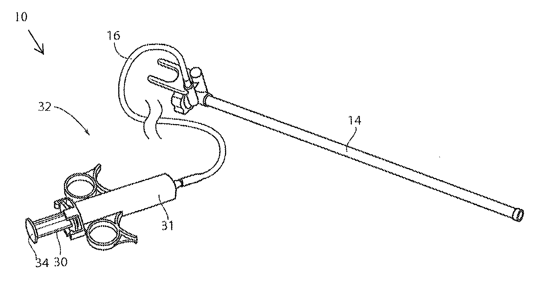
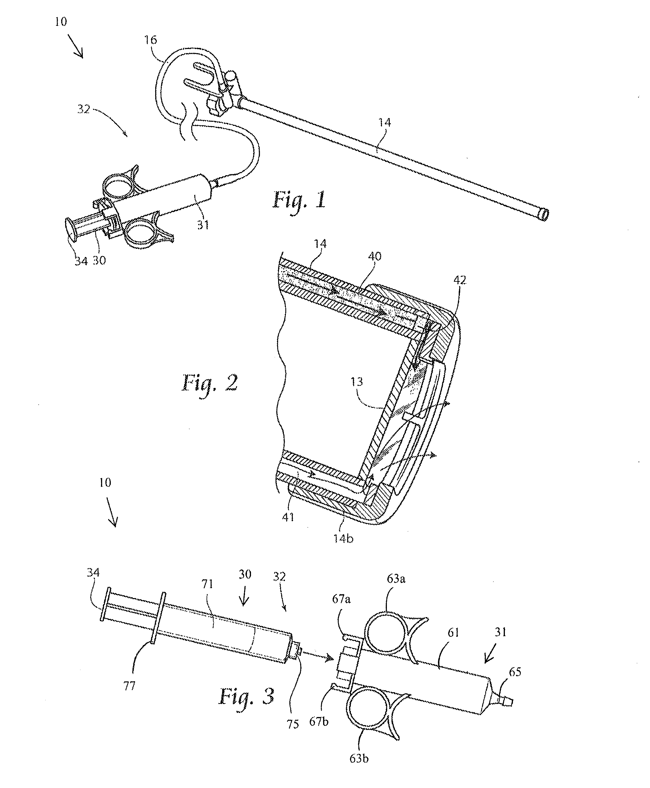
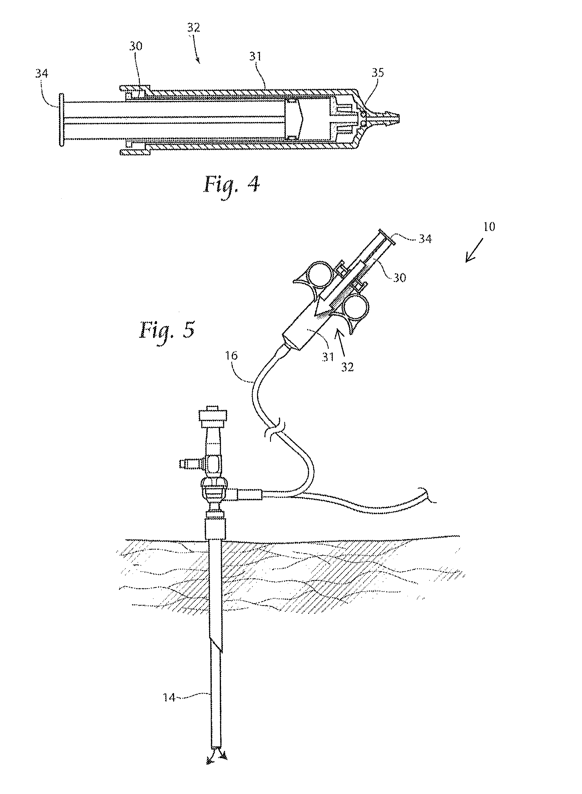
[0033]Described herein is a laparoscopic sheath including a lumen for cleaning fluid and a valve configured to control the release of fluid from the lumen. The valve can advantageously retain the fluid in the lumen until sufficient pressure is applied to open the valve and dispense the fluid. The valve can be at the distal end of the lumen and can be configured to self-close when the dispensing pressure is relieved. Also described herein is a fluid delivery system configured to transfer fluid from a user-actuated syringe to the distal end of a surgical instrument, such as a laparoscope. The fluid delivery system can include a line-pressure relief system that, in conjunction with the valve, prevents secondary drips of fluid from leaving the lumen and, for example, depositing on the lens of a laparoscope.

[0034]Although the disclosure hereof is detailed and exact to enable those skilled in the art to practice the invention, the physical embodiments herein disclosed merely exemplify the...


PUM


Abstract

Systems and methods make use of a fluid dispensing control apparatus having a sheath, a tubing system, and a fluid source to facilitate control of fluid during intra-operative defogging, surgical debris deflection, and cleaning of a laparoscope lens during minimally invasive surgery. The sheath has at least one lumen for providing fluid to the distal end of the sheath to clean the laparoscope. At the end of the lumen is a one-way control valve to prevent the uncontrolled flow of fluid from the lumen. The apparatus may also have a syringe assembly wherein a syringe is inserted into a syringe mating mechanism having a gasket which can facilitate the immediate relief of pressure in the fluid lumen once the pressure on the syringe plunger is released.

Description

CROSS REFERENCE TO RELATED APPLICATIONS[0001]This application claims priority to U.S. Provisional Application No. 61 / 783,847, titled “Fluid Dispensing Control,” and filed Mar. 14, 2013, the entirety of which is incorporated by reference.INCORPORATION BY REFERENCE[0002]All publications and patent applications mentioned in this specification are herein incorporated by reference to the same extent as if each individual publication or patent application was specifically and individually indicated to be incorporated by reference.FIELD[0003]The invention generally relates to an apparatus for controlling the dispensing of fluids, and in particular, a dispensing control for fluid being provided to a distal end of a surgical scope, such as, a laparoscope, in order to maintain and improve visualization.BACKGROUND[0004]Minimally invasive surgical procedures utilizing surgical scopes are desirable because they often provide one or more of the following advantages: reduced blood loss, reduced po...

Claims


Application Information

Patent Timeline
Patent Type & Authority Applications(United States)
IPC IPC(8): A61B1/015A61B1/12A61M5/31A61B1/00A61B1/313
CPCA61B1/12A61B1/00135A61B1/015A61B1/00128A61B1/126A61B1/3132A61M5/3134A61B1/00091A61B1/00096
Inventor DRACH, GREGORY P.POLL, WAYNE L.
Owner FLOSHIELD INC
Learn More