

Insulating element
- Summary
- Abstract
- Description
- Claims
- Application Information
AI Technical Summary
Benefits of technology
Problems solved by technology
Method used
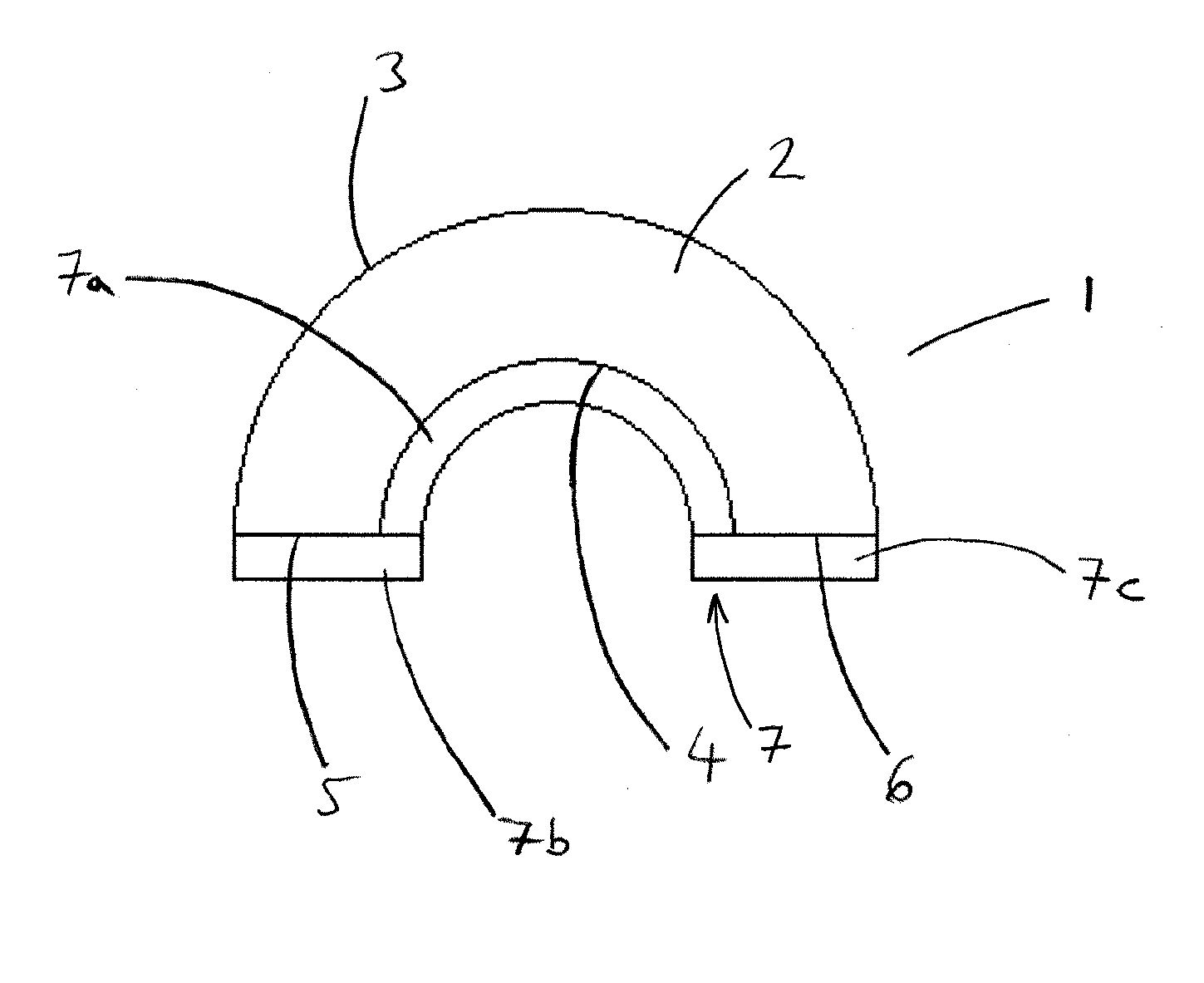
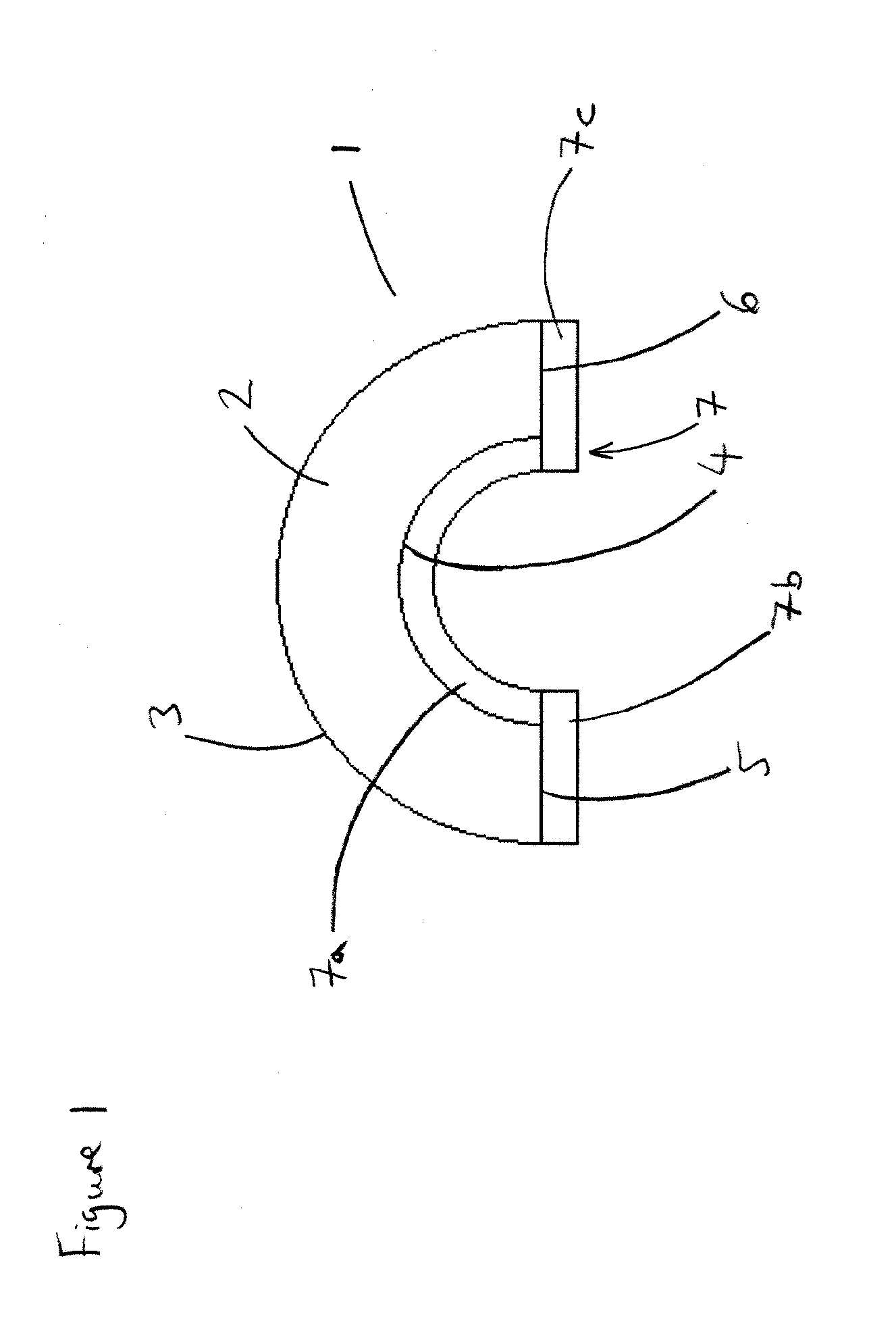
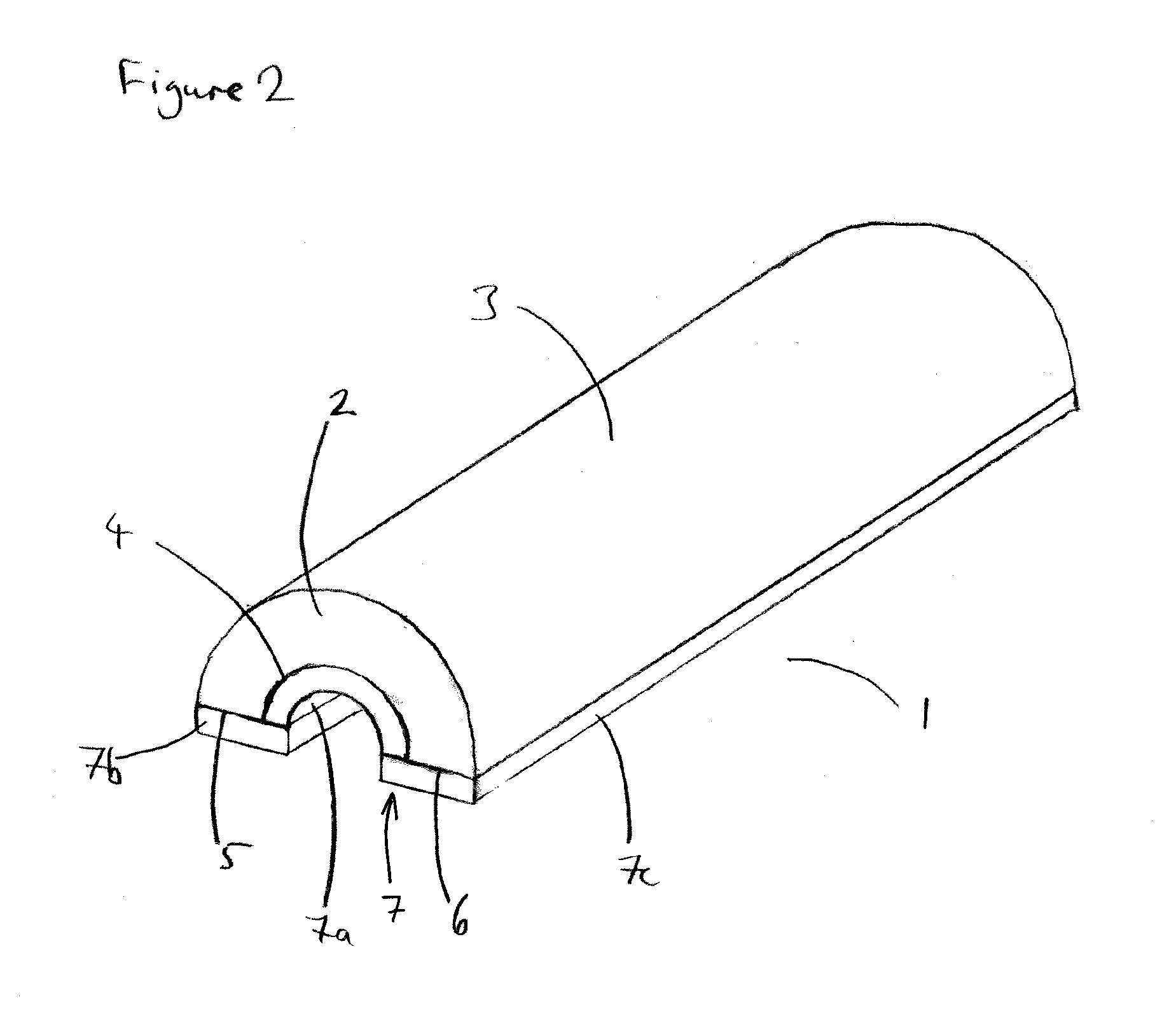
Image

Examples
example 1
Comparative
[0104]100.0 g of a commercially available composition of diphenylmethane-4,4′-diisocyanate and isomers and homologues of higher functionality, and 100.0 g of a commercially available polyol formulation were mixed by propellers for 20 seconds at 3000 rpm. The material was then placed in a mold to foam, which took about 3 min. The following day, the sample was weighed to determine its density and the compression strength and compression modulus of elasticity were measured according to European Standard EN 826:1996.
[0105]Compressive strength: 1100 kPa
[0106]Compression modulus of elasticity: 32000 kPa
example 2
[0107]100.0 g of the same commercially available polyol formulation as used in Example 1 was mixed with 200.0 g ground stone wool fibres, over 50% of which have a length less than 64 micrometres, for 10 seconds. Then 100.0 g of the commercially available composition of diphenylmethane-4,4′-diisocyanate was added and the mixture was mixed by propellers for 20 seconds at 3000 rpm. The material was then placed in a mold to foam, which took about 3 min. The following day, the sample was weighed to determine its density and the compression strength and compression modulus of elasticity were measured according to European Standard EN 826:1996.
[0108]Compressive strength: 1750 kPa
[0109]Compression modulus of elasticity: 95000 kPa
example 3
Comparative
[0110]100.0 g of the same commercially available polyol formulation as used in Examples 1 and 2 was mixed for 10 seconds with 50.0 g stone fibres having a different chemical composition from those used in Example 2 and having an average length of 300 micrometres. 100.0 g of the commercially available composition of diphenylmethane-4,4′-diisocyanate was added. The mixture was then mixed by propellers for 20 seconds at 3000 rpm. The material was placed in a mold to foam, which takes about 3 min. The following day, the sample was weighed to determine its density and the compression strength and compression modulus of elasticity were measured according to European Standard EN 826:1996.
[0111]Compressive strength: 934 kPa
[0112]Compression modulus of elasticity: 45000 kPa
PUM
| Property | Measurement | Unit |
|---|---|---|
| Length | aaaaa | aaaaa |
| Length | aaaaa | aaaaa |
| Length | aaaaa | aaaaa |
Abstract
Description
Claims
Application Information