
Space laser film preparation method

A laser thin film and space technology, which is applied in vacuum evaporation coating, coating, sputtering coating, etc., can solve the problems of poor stability of laser thin film, achieve reduced surface and subsurface defects, small spectral shift, high The effect of dimensional stability

Active Publication Date: 2021-01-26
SHANGHAI INST OF OPTICS & FINE MECHANICS CHINESE ACAD OF SCI
View PDF11 Cites 0 Cited by
  • Summary
  • Abstract
  • Description
  • Claims
  • Application Information

AI Technical Summary

Problems solved by technology

[0006] The purpose of the present invention is to provide a space laser thin film preparation method, and proposes a full-process technical solution including removing substrate surface pollutants and subsurface defects, adding an anti-radiation protective layer, and coating on the substrate, effectively solving the problem of laser thin film in space. The problem of poor stability in the environment

Method used


Image

  • Space laser film preparation method
  • Space laser film preparation method
  • Space laser film preparation method

Examples


Embodiment 1

[0033] Embodiment 1: take quartz glass as substrate, Al 2 o 3 For the film material, SiO 2 Prepare a 1064nm AR coating for the protective layer material.

[0034] Clean the substrate ultrasonically for 10-30 minutes, then rinse it with deionized water, and finally dry it with high-purity nitrogen; scrub the vacuum chamber inside the coating machine, and perform vacuum pumping; put the substrate into the coating machine, and close the vacuum chamber door , carry out vacuum pumping again, and control the background vacuum degree of the vacuum chamber in the coating machine to be 2×10 -6 Pa, heating the substrate to keep the temperature at 80°C; ion beam etching is performed on the substrate before coating, and the Ar ion source is used to bombard the substrate, the Ar ion source voltage used is 650V, and the etching depth is 200nm; dual ion beam sputtering is used The equipment is used to coat the above-mentioned treated substrates, the main ion source voltage is 1250V, argon...

Embodiment 2

[0037] Embodiment 2: take quartz glass as substrate, Ta 2 o 5 For the film material, SiO 2 Prepare a high reflection film for the protective layer material.

[0038] Clean the substrate ultrasonically for 10-30 minutes, then rinse it with deionized water, and finally dry it with high-purity nitrogen; scrub the vacuum chamber inside the coating machine, and perform vacuum pumping; put the substrate into the coating machine, and close the vacuum chamber door , carry out vacuum pumping again, and control the background vacuum degree of the vacuum chamber in the coating machine to be 2×10 -6 Pa, heating the substrate to keep its temperature at 80°C; ion beam etching is performed on the substrate before coating, the substrate is bombarded with Ar ion source, the voltage of Ar ion source is 650V, and the etching depth is 200nm; dual ion beam sputtering equipment is used Coating on the above treated substrate, the main ion source voltage is 1250V, using argon as the main ion sourc...


PUM


Abstract

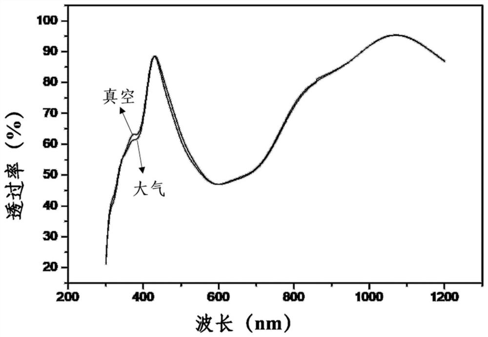
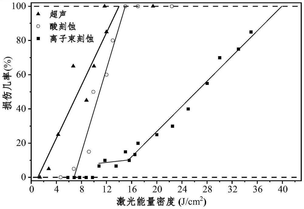
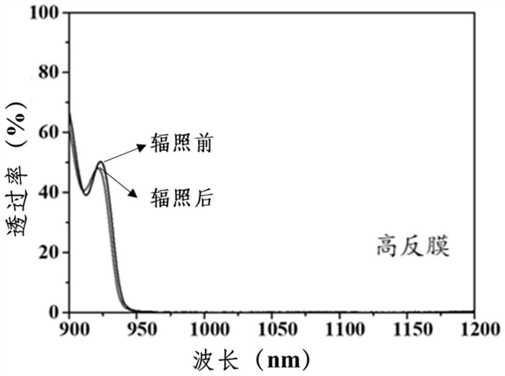
The invention belongs to the technical field of optical films, and particularly relates to a space laser film preparation method. The method provides the whole process technical scheme for preparing aspace laser film. The method comprises the following steps that pollutants and sub-surface defects on the surface of a substrate are removed, an anti-radiation protective layer is added, the substrate is coated with the film. The technical scheme and implementation way of each link are defined, the defects on the surface and sub-surface of the substrate are greatly reduced by using the film prepared by the method, the refractive index of the film can reach the level of a bulk material, spectral offset is small in an atmospheric-vacuum environment, the film is not liable to be affected by space particle irradiation, the film has a high laser damage threshold value, and the situation that a conventional laser film is not suitable for the space environment is avoided.

Description

technical field [0001] The invention belongs to the technical field of optical thin films, and in particular relates to a method for preparing space laser thin films. Background technique [0002] With the continuous deepening of human exploration of the space environment and the continuous development of lasers, space laser systems have become an important tool in space missions. As one of the weakest components in the optical system, the optical film cannot be repaired or replaced once it is damaged during orbital operation, so its stability and service life are crucial to the entire system. In space, there are special environmental factors such as vacuum, high and low temperature alternation, and high-energy particle radiation that are different from the ground. For space applications, laser thin films must not only resist laser damage, but also have good stability in the space environment. , which puts forward higher requirements for optical films. [0003] However, th...

Claims


Application Information

Patent Timeline
IPC IPC(8): C23C14/34C23C14/02C23C14/54C23C14/08C23C14/10
CPCC23C14/3442C23C14/022C23C14/54C23C14/081C23C14/10C23C14/083C23C14/0036
Inventor 王胭脂王志皓张宇晖陈瑞溢许贝贝朱晔新赵娇玲邵宇川易葵贺洪波邵建达
Owner SHANGHAI INST OF OPTICS & FINE MECHANICS CHINESE ACAD OF SCI
Learn More