

Magnetic Ranging To An AC Source While Rotating
a technology of rotating and magnetic range, which is applied in the direction of instruments, surveying, and borehole/well accessories, etc., can solve the problems of high cost and time-consuming of magnetic range operations
- Summary
- Abstract
- Description
- Claims
- Application Information
AI Technical Summary
Benefits of technology
Problems solved by technology
Method used
Image

Examples
embodiment 100
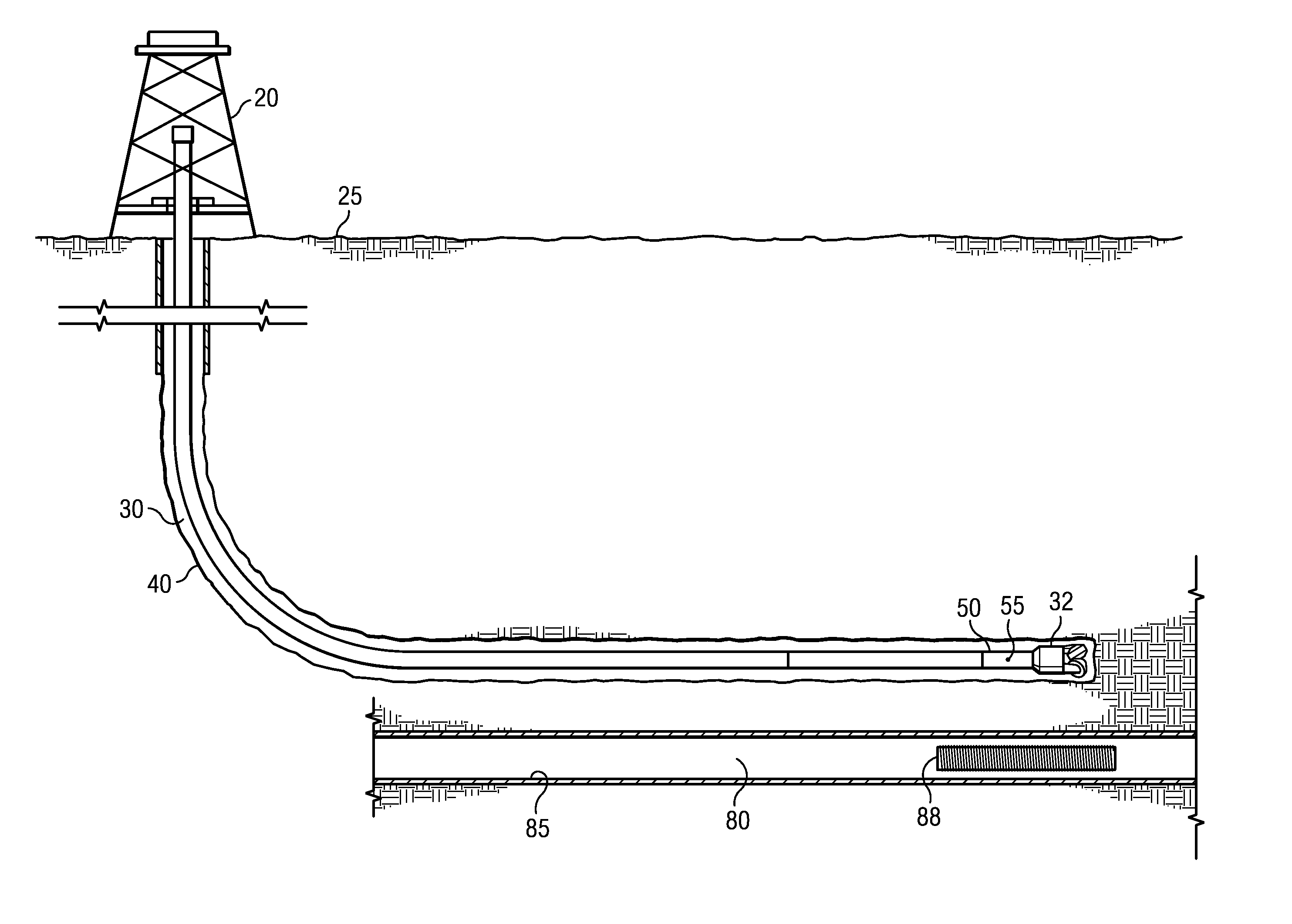
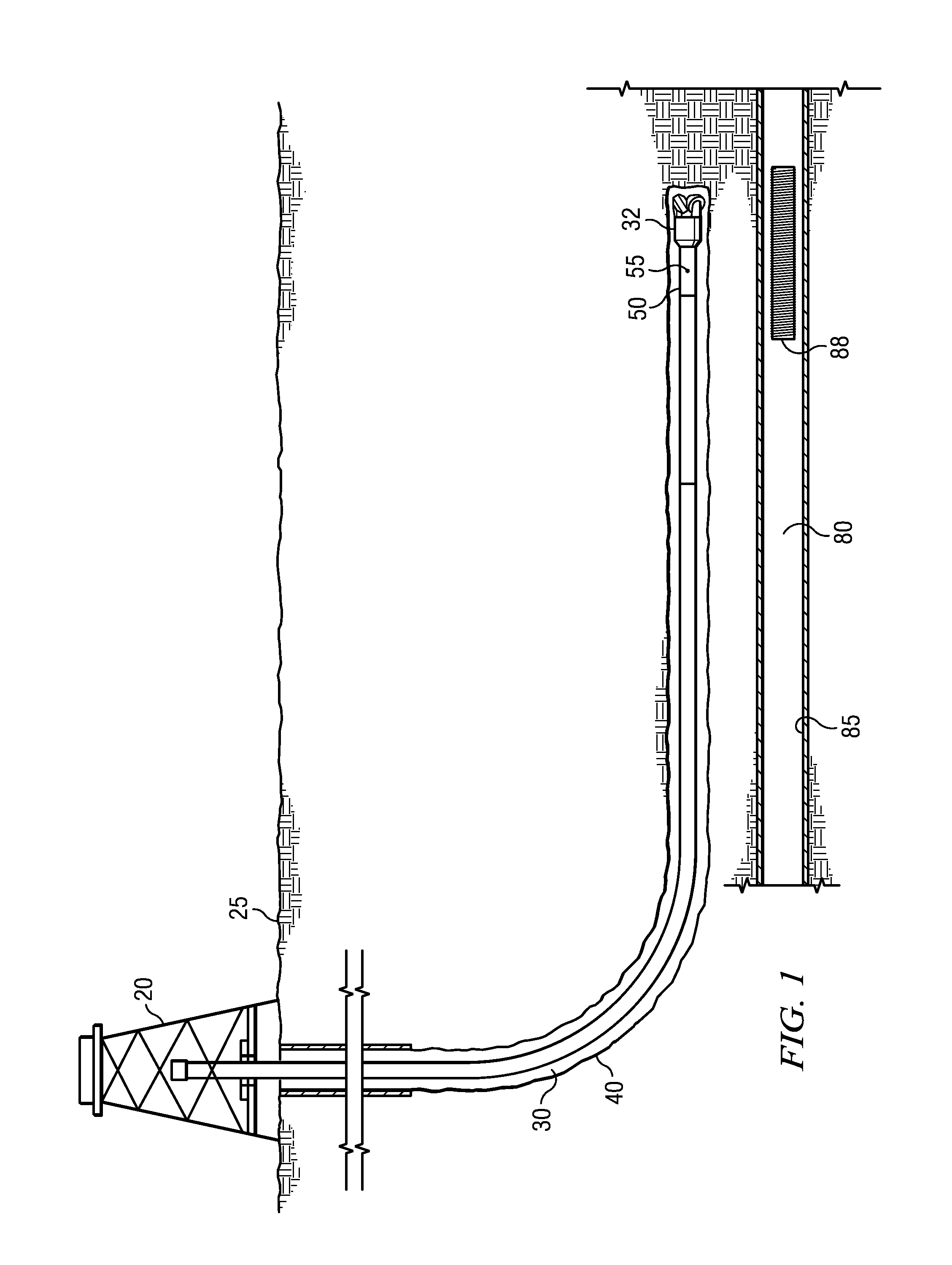
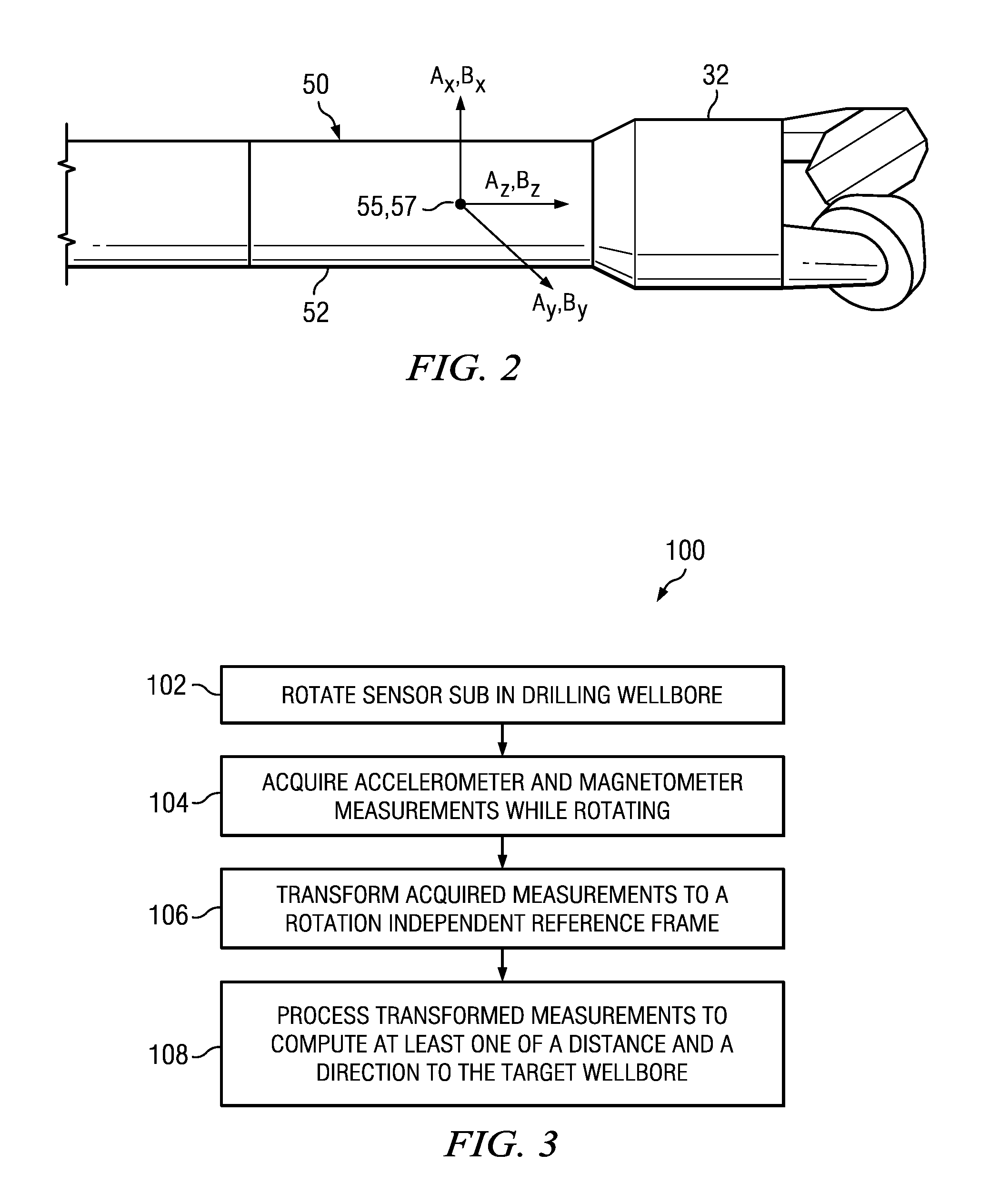
[0028]FIG. 3 depicts a flow chart of one disclosed method embodiment 100. A sensor sub (e.g., sub 50) including accelerometers and magnetometers is rotated in a drilling well at 102 in sensory range of magnetic flux emanating from a target wellbore. Accelerometer and magnetometer measurements are acquired at 104 while rotating in 102. The acquired transverse magnetometer measurements may be transformed at 106 to a reference frame that is independent of the sensor rotation in 102. The transformed measurements may then be processed at 108 to compute at least one of a distance and a direction from the drilling well to the target well.
[0029]During rotation at 102, the transverse sensor (accelerometers Ax and Ay and magnetometers Bx and By) measurements may be expressed mathematically, for example, as follows:
Ax=−Axy·sin T (1)
Ay=−Axy·cos T (2)
Bx=Bxy·sin M (3)
By=Bxy·cos M (4)
[0030]where Axy represents the transverse component of the acceleration (e.g., due to gravity), Bxy represents ...
embodiment 120
[0062]FIG. 9 depicts a flow chart of another disclosed method embodiment 120. A sensor sub including a magnetic field sensor (such as a tri-axial magnetometer set) is rotated in a drilling wellbore at 122 in sensory range of AC magnetic flux emanating from a target wellbore (note that the sensor sub may optionally, but does not necessarily, include accelerometers). Magnetic sensor measurements are acquired at 124 while rotating in 122 to obtain a magnetic field vector. The measured magnetic field vector is processed at 126 to compute at least one of (i) the amplitude of the transverse component of the AC magnetic flux emanating from the target wellbore and (ii) the angle between the transverse component of the AC magnetic flux emanating from the target wellbore and the transverse component of the Earth's magnetic field. The computed quantity (or quantities) may then be further processed at 128 to compute at least one of a distance and a direction from the drilling well to the target...
embodiment 140
[0080]FIG. 11 depicts a flow chart of yet another disclosed method embodiment 140. A sensor sub including a magnetic field sensor (such as a tri-axial magnetometer set) is rotated in a drilling wellbore at 142 in sensory range of AC magnetic flux emanating from a target wellbore (note that the sensor sub may optionally, but does not necessarily include accelerometers). Magnetic sensor measurements are acquired at 144 while rotating in 142 to obtain a magnetic field vector. The measured magnetic field vector is processed at 146 to compute a difference between an instantaneous rotation rate and an average rotation rate of the sensor sub. The computed difference is processed at 148 to compute a direction from the drilling well to the target well. The difference may be optionally further processed at 150 to compute a distance to the target well.
[0081]At each instant (i.e., at each magnetometer measurement interval—such as 10 millisecond), an apparent magnetic toolface may be computed, f...
PUM
 Abstract
Description
Claims
Application Information