
Power plant & energy storage system for provision of grid ancillary services

Active Publication Date: 2015-12-31
VESTAS WIND SYST AS
View PDF2 Cites 59 Cited by
  • Summary
  • Abstract
  • Description
  • Claims
  • Application Information

AI Technical Summary

Benefits of technology

The patent describes a power plant that uses wind power and energy storage to provide stability to the power system. The plant can adjust its power output without causing mechanical resonances and can damp out disturbances in the grid. This helps to stabilize the electrical grid. The technical effects of this invention include improved wind power utilization and improved stability and control of the power system.

Problems solved by technology

Under the conventional approach, operational control is not necessarily optimized from the overall perspective of the power plant; that is, from the perspective of the wind power plant and the energy storage as a system.
For example, the lack of coordinated control actions can lead to unnecessary consumption of the lifetime of the energy storage device and / or the lifetime of the wind turbines.
As yet another example, the lack of coordinated control actions may yield wind turbine operation at unnecessarily large actuator rates of change to, for example, the rotor pitch.
By operating the wind turbines without directly acknowledging the conditions of the energy storage device, system-level objectives are in general not optimized.
The need for ancillary services in power systems increases as wind power penetration grows, since wind power introduces balancing issues (among others) due to its natural variability and wind turbine technologies do not naturally behave as synchronous machines.
Additionally, with increasing wind power penetration, decommissioned conventional plants are not replaced, which further reduces the stability and control capability of the power system.
Power systems with high amounts of renewable generation must address the future sources of ancillary services—power system stabilising features—as operating non-renewable generation simply as spinning reserve is expected to be prohibitively expensive.

Method used


Image

  • Power plant & energy storage system for provision of grid ancillary services
  • Power plant & energy storage system for provision of grid ancillary services
  • Power plant & energy storage system for provision of grid ancillary services

Examples


Embodiment Construction

[0062]The present invention will now be explained in further details. While the invention is susceptible to various modifications and alternative forms, specific embodiments have been disclosed by way of examples. It should be understood, however, that the invention is not intended to be limited to the particular forms disclosed. Rather, the invention is to cover all modifications, equivalents, and alternatives falling within the spirit and scope of the invention as defined by the appended claims.

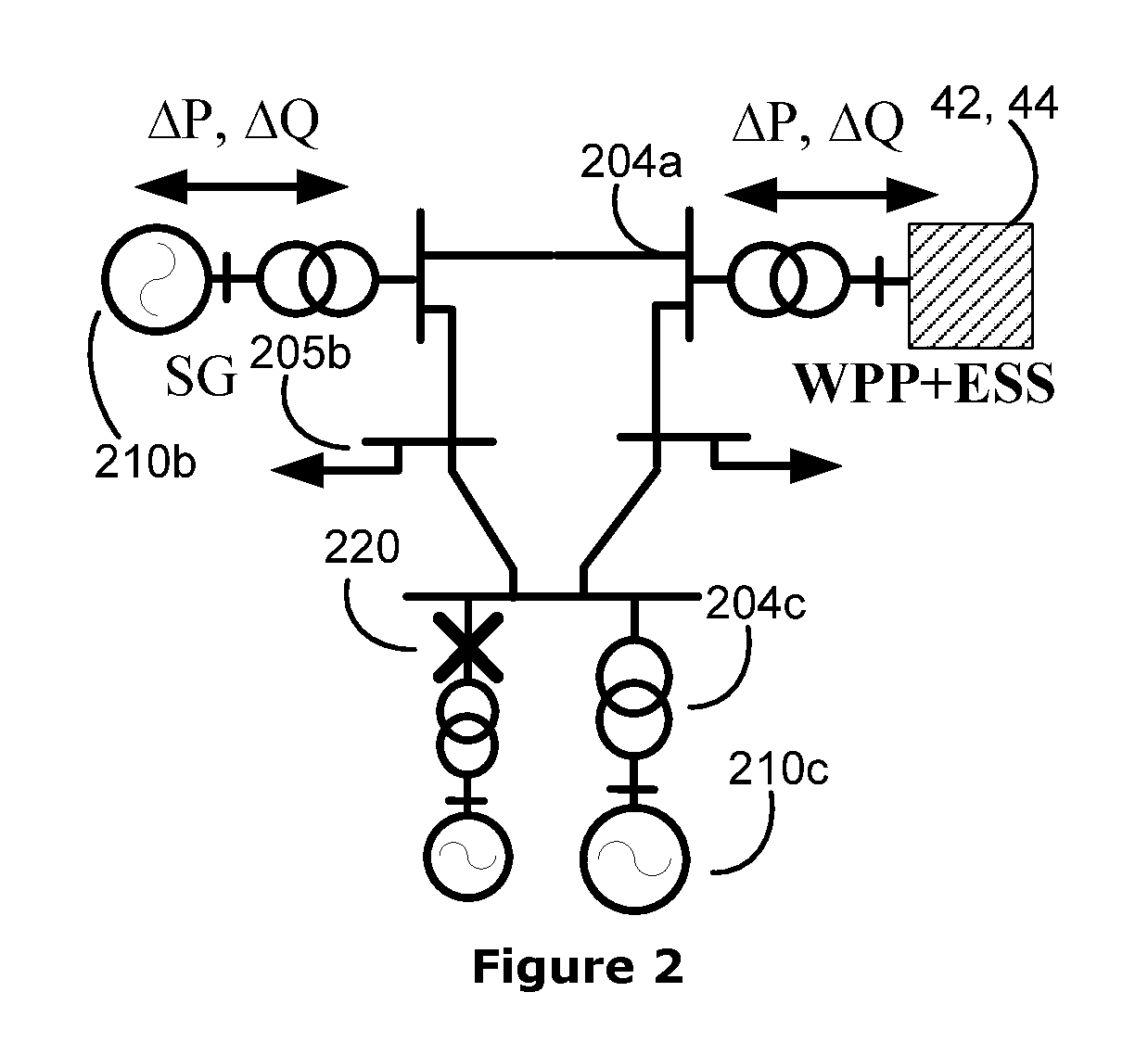
[0063]Power Systems require operations and controls necessary for its stability at several time scales, which are normally referred to as ancillary services, e.g. voltage control, frequency support, power (spinning) reserve, power dispatch and others. Traditionally these ancillary services are supplied by conventional power plants normally equipped with synchronous generators.

[0064]As stated in the summary power systems with high amounts of renewable generation must address the future sourc...


PUM


Abstract

The present invention relates to method for operating a power plant, with at least one wind turbine generator arranged for supplying power to an electrical grid, at least one energy storage device arranged for supplying power to the electrical grid, and a power plant controller, the method comprises, measuring repetitively measurement sets of at least one electrical parameter from the electrical grid, and calculating, in respect the measurement sets of the at least one electrical parameter, a change in active and / or a required change in reactive power at a point of common coupling, and calculating and dispatching of a first control reference signal to the at least one wind turbine generator and a second control reference signal to the at least one energy storage device, for providing ancillary service functionalities to the electrical grid. The invention also relates to a power plant with at least one wind turbine generator for supplying power to an electrical grid, at least one energy storage device for supplying power to the electrical grid, and a power plant controller for providing ancillary service functionalities to the electrical grid.

Description

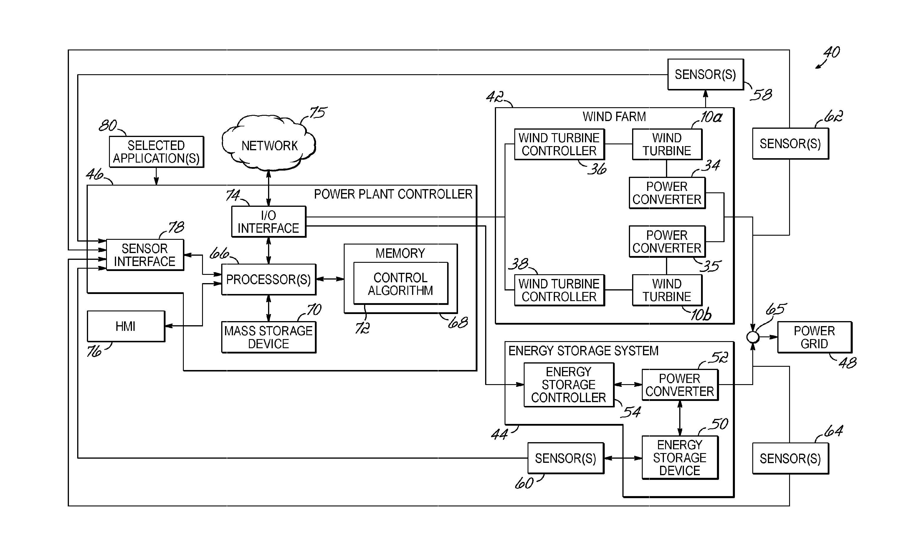
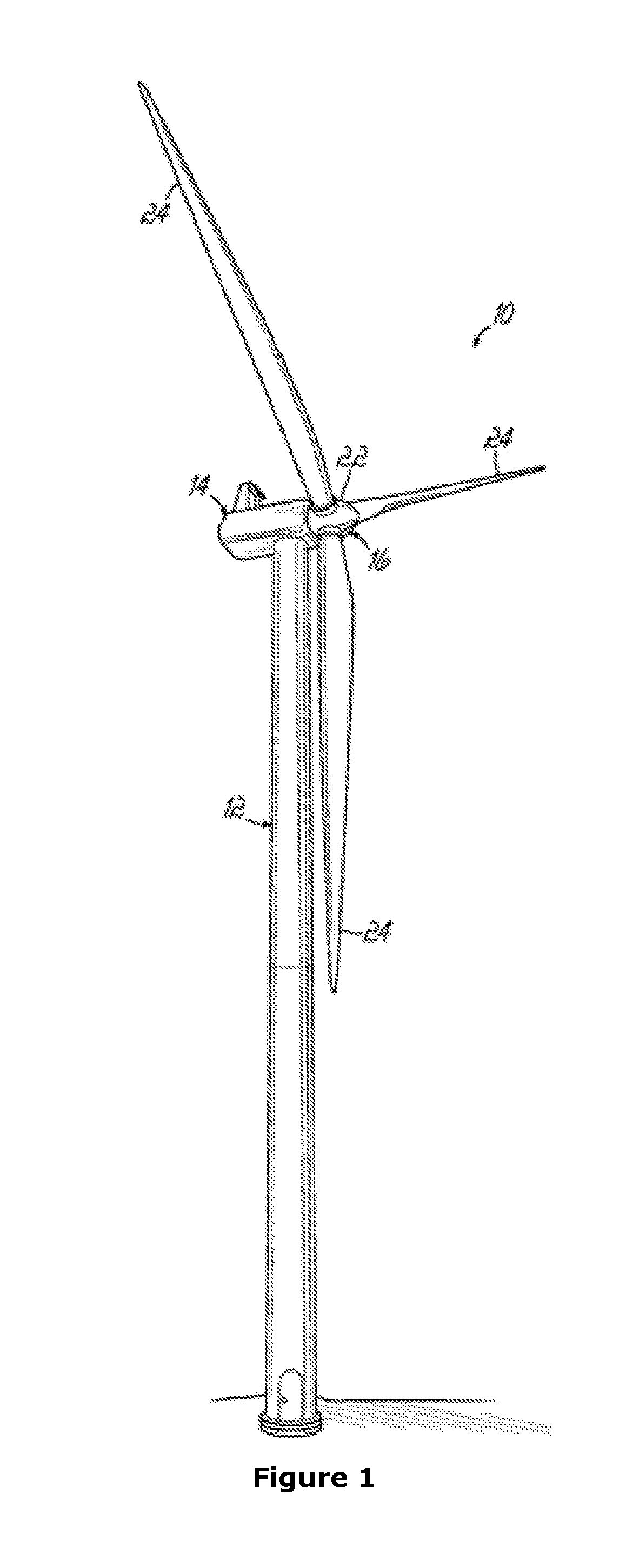
FIELD OF THE INVENTION[0001]The present invention generally relates to electrical power generation and, more specifically, to methods and systems for use in optimizing the power output produced by a power plant that includes a power generating unit and an energy storage device.BACKGROUND OF THE INVENTION[0002]A wind power plant, or wind park, includes a group of wind turbines that operate collectively as a power plant that generates a power output to a power grid. Wind turbines can be used to produce electrical energy without the necessity of fossil fuels. Generally, a wind turbine is a rotating machine that converts the kinetic energy of the wind into mechanical energy and the mechanical energy subsequently into electrical power.[0003]A wind power plant could also include an energy storage device, such as one or more rechargeable batteries or flywheels, that are also linked to the power grid and that may assist with meeting requirements on the power production by the power plant. W...

Claims


Application Information

Patent Timeline
IPC IPC(8): H02P9/14H02J3/24H02J3/38H02J3/28
CPCH02J3/24Y02P90/50H02J3/386Y02E70/30Y02E10/763Y02E10/766H02J3/38H02P9/14F03D7/0284F03D7/045F05B2270/337F05B2270/404F03D9/11Y02E10/723H02J3/28H02J2300/28H02J2300/22H02J3/381Y02E10/72Y02E10/76H02J3/32H02J3/30H02J3/40
Inventor TARNOWSKI, GERMÁN CLAUDIOKJÆR, PHILIP CARNELÆRKE, RASMUSIOV, FLORINTEODORESCU, REMUSADAMCZYK, ANDRZEJ
Owner VESTAS WIND SYST AS
Learn More