Gas-blowing-hole array structure and soldering apparatus

a technology of array structure and gas-blowing hole, which is applied in the direction of soldering apparatus, manufacturing tools, non-electric welding apparatus, etc., can solve the problem of board cooling, and achieve the effect of high reliability and high reliability

Active Publication Date: 2015-12-31
SENJU METAL IND CO LTD
View PDF23 Cites 11 Cited by
  • Summary
  • Abstract
  • Description
  • Claims
  • Application Information

AI Technical Summary

Benefits of technology

[0019]According to the gas-blowing-hole array structure of this invention, when making a criterion a center portion of the nozzle layout region of the gas-blowing holes plate in which the width direction and the conveying direction are orthogonal to each other, in the upper and lower divided sections of the opposite sides of the center portion, the first arrangement pattern of the gas-blowing holes and a second arrangement pattern of the gas-blowing holes, which is an inverse first arrangement pattern thereof, are provided so that the arrangement patterns that are arranged on a diagonal line in the nozzle layout region are identical.
[0020]By such a structure, the second arrangement pattern of the gas-blowing holes can be arranged so that it is self-matched to be line symmetry with the first arrangement pattern thereof in the right and left divided sections relative to the center portion of the nozzle layout region in which the width direction and the conveying direction are orthogonal to each other. Therefore, it is possible to blow the heated air to the whole surface of the conveyed member almost concentrically from each of the arrangement patterns of the gas-blowing holes i

Problems solved by technology

However, the heated air, which is heated by the heater(s), blows in the preliminary heating zone and the heating zone while in this cooling zone, the cooling water pipes an

Method used


Image

  • Gas-blowing-hole array structure and soldering apparatus
  • Gas-blowing-hole array structure and soldering apparatus
  • Gas-blowing-hole array structure and soldering apparatus

Examples


Embodiment Construction

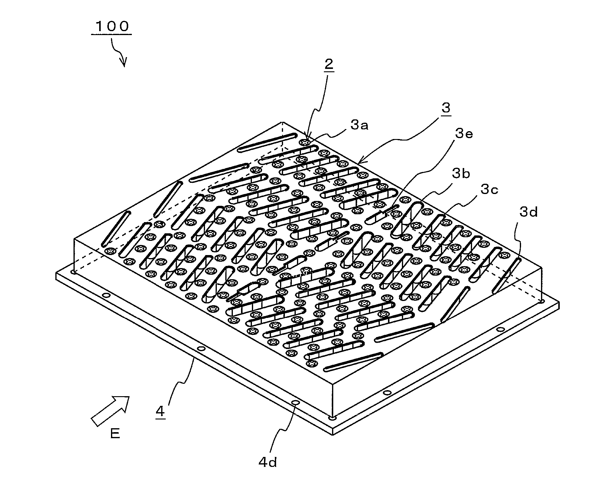
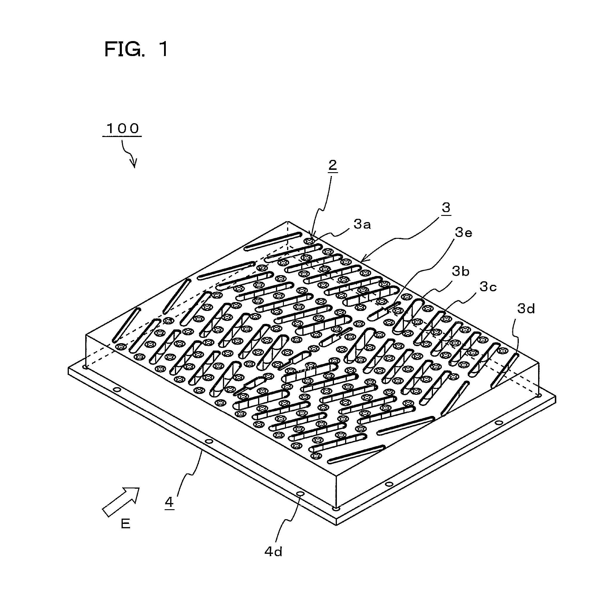
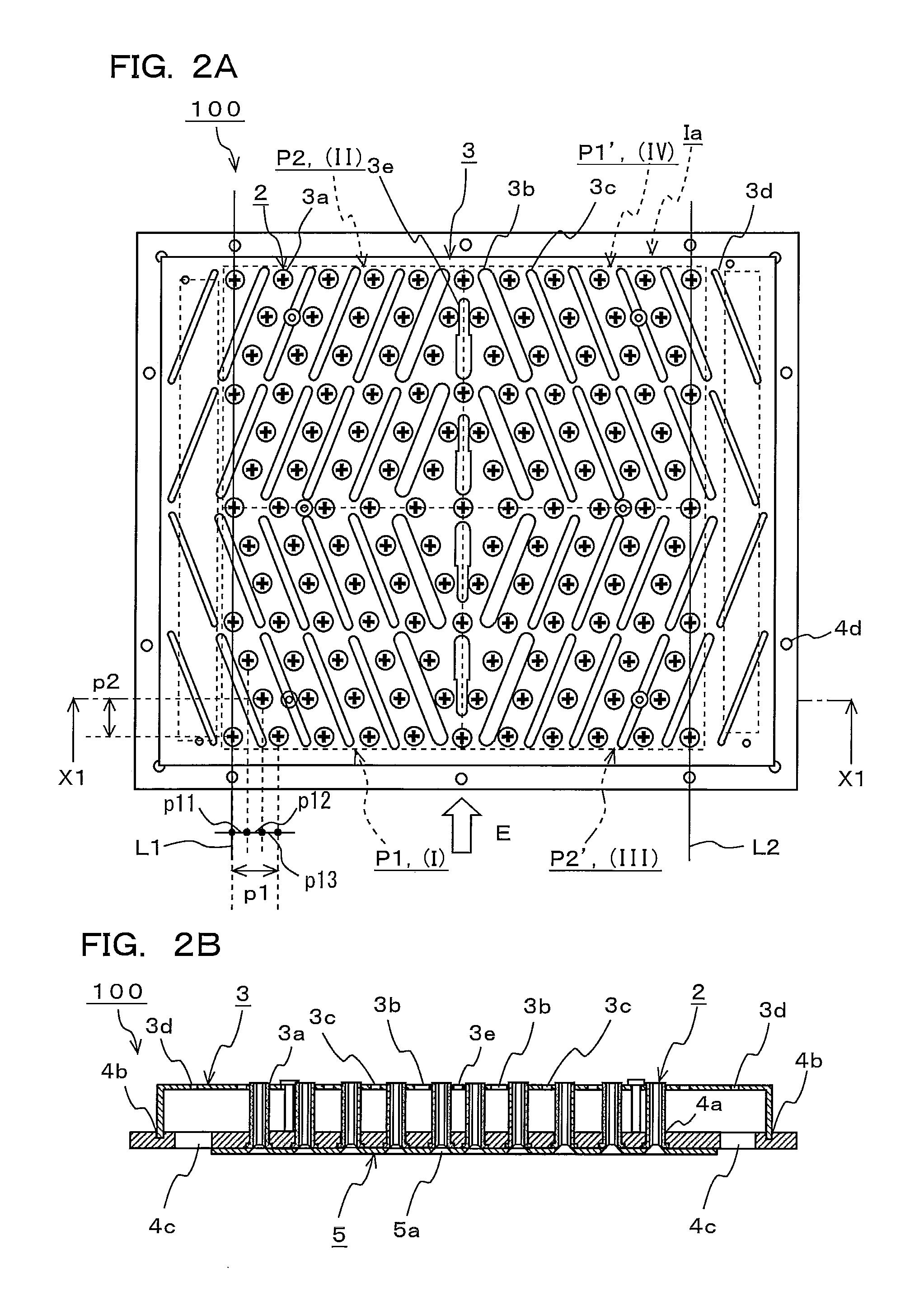
[0050]This invention has solved these problems and has an object to present a gas-blowing-hole array structure and a soldering apparatus, which enable the heated air to be blown to the whole surface of the conveyed member such as a printed circuit board, a semiconductor wafer or the like almost concentrically by devising the arrangement of the gas-blowing holes and allow the whole surface of conveyed member to be very uniformly heated. Further, it has an object to present a gas-blowing-hole array structure and a soldering apparatus, which allow the holes plate in which gas-blowing holes and gas-intake-ports are arranged to be used as common parts of top and bottom surfaces in the furnace. Additionally, in this invention, soldering by blowing any heated gas to the board or cooling the board by blowing any cooled gas to the soldered board will be referred as “soldering processing”.

[0051]The following will describe the gas-blowing-hole array structure and the soldering apparatus as emb...


PUM


Abstract

In a gas-blowing-hole array structure, which enables gas to be blown to the whole surface of the conveyed member such as a printed circuit board, a semiconductor wafer or the like almost concentrically and allows the whole surface of conveyed member to be very uniformly heated or cooled, a nozzle pattern P2 of blowing nozzles 2 is arranged to be line symmetry with a nozzle pattern P1 of the blowing nozzles 2 in upper and lower divided sections of one side of the nozzle cover 3 relative to a center portion thereof that is orthogonal to a conveying direction, as shown in FIG. 1. In order for the arrangement patterns diagonally arranged in the nozzle cover 3 to become identical, the nozzle pattern P1 is arranged to be line symmetry with the nozzle pattern P2 of the blowing nozzles 2 in upper and lower divided sections of the other side of the nozzle cover 3.

Description

TECHNICAL FIELD[0001]The present invention relates to a gas-blowing-hole array structure and a soldering apparatus, the gas-blowing-hole array structure being applicable to a nozzle device that blows heated air to a conveyed member such as a printed circuit board, a semiconductor wafer or the like in a heating zone and blows cooled air to the member in a cooling zone and a reflow furnace mounting the nozzle device.BACKGROUND[0002]When soldering electronic components on the printed circuit board, the reflow furnace which solders them by fusing solder paste in which solder powder and flux are mixed has been often used in recent years. The reflow furnace contains a preliminary heating zone, a heating zone and a cooling zone within a tunnel muffle. The preliminary heating zone and the heating zone are provide with heaters for heating and the cooling zone is provided with a cooling mechanism being constituted of cooling water pipes, cooling fun or the like.[0003]The reflow furnace is pro...

Claims


Application Information

Patent Timeline
IPC IPC(8): H05K3/34B23K3/04B23K3/08B23K1/00
CPCB23K1/008B23K3/04B23K1/0016H05K3/3494H05K2203/04B23K1/012B23K2101/42B23K3/082H05K2203/081
Inventor HIYAMA, TSUTOMU
Owner SENJU METAL IND CO LTD
Why Eureka
Try Eureka