Apparatus and method for providing gases to a user

Active Publication Date: 2016-01-07
FISHER & PAYKEL HEALTHCARE LTD
View PDF6 Cites 7 Cited by
  • Summary
  • Abstract
  • Description
  • Claims
  • Application Information

AI Technical Summary

Benefits of technology

[0004]The connector can be formed such that it is located entirely outside of the tubing such that the end of the tubing is not obstructed by the connector. Such a configuration advantageously allows use of the tubing with standard barbed air connections even with the connector installed on the end of the tubing.
[0005]The connector can be mechanically secured (e.g., snap fit)

Problems solved by technology

In situations where the connectors are joined to the tubing without the use of adhesives, it has b

Method used


Image

  • Apparatus and method for providing gases to a user
  • Apparatus and method for providing gases to a user
  • Apparatus and method for providing gases to a user

Examples


Embodiment Construction

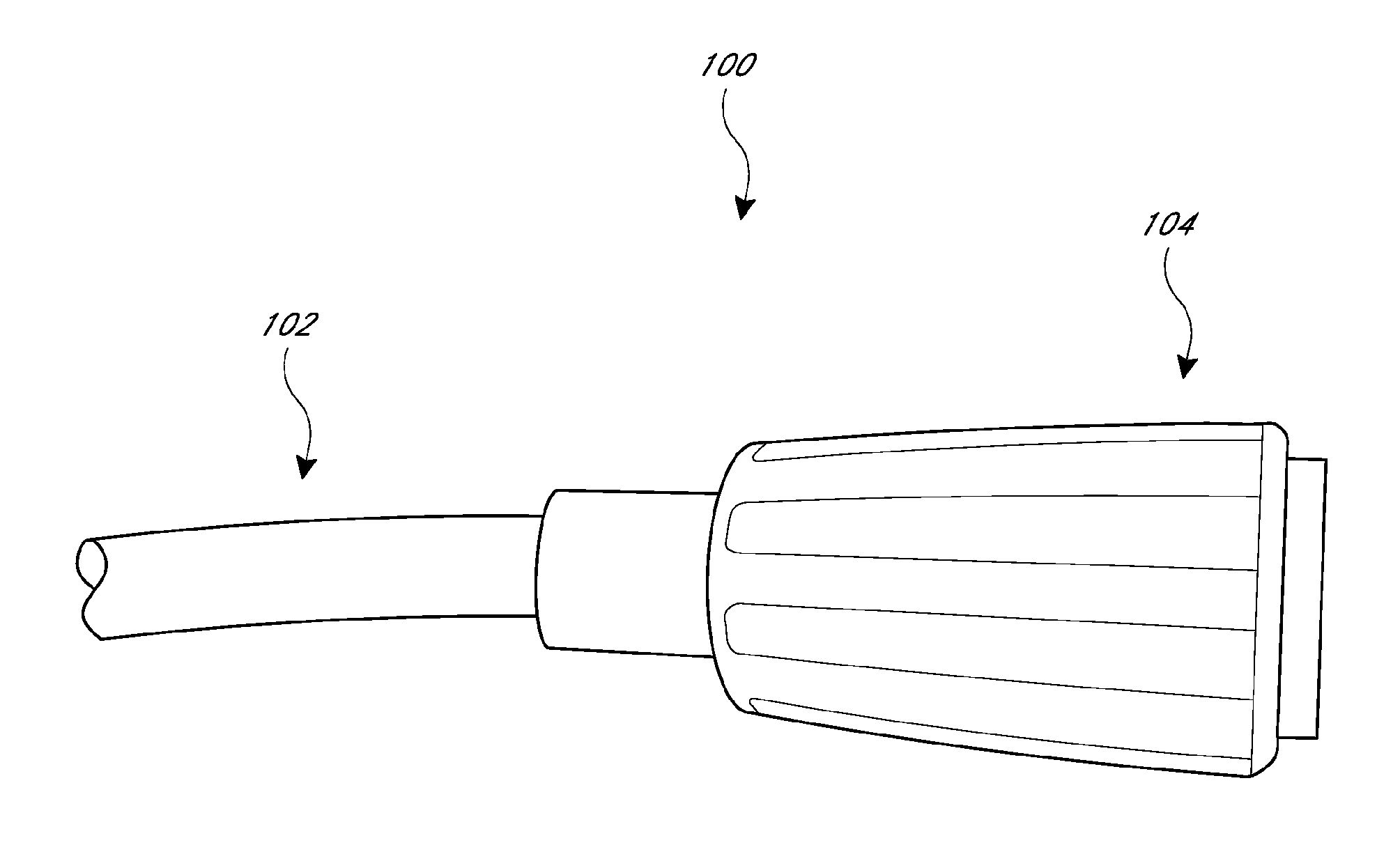
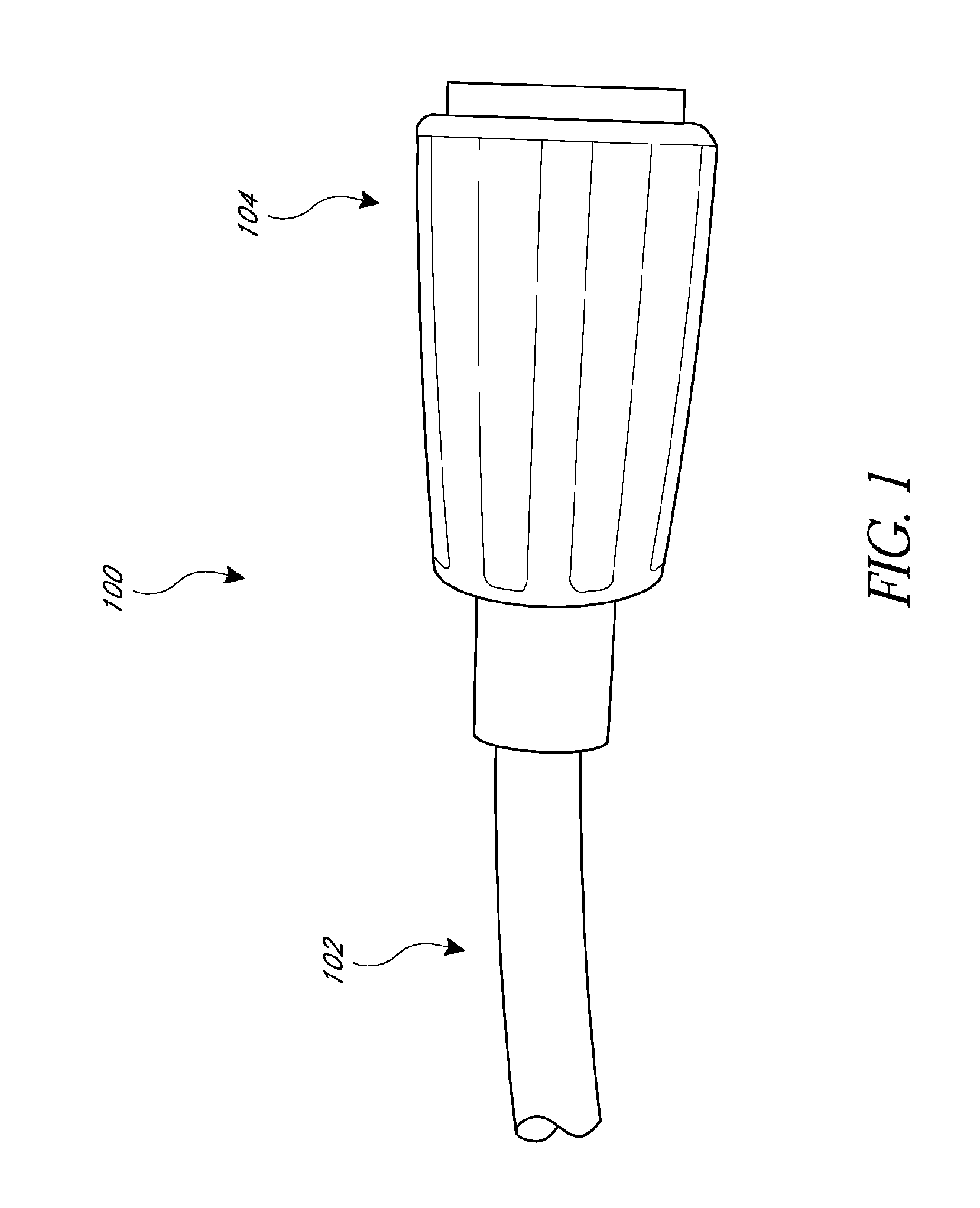
[0024]With reference initially to FIG. 1, a connector and tubing combination 100 is illustrated therein. The combination 100 generally comprises a segment of tubing 102 and a connector assembly 104. When assembled, the combination 100 can be used to couple the tubing to a connector of another component. In some configurations, the combination can couple to a proprietary connector while also enabling connection to a standard barbed connection, for example but without limitation.

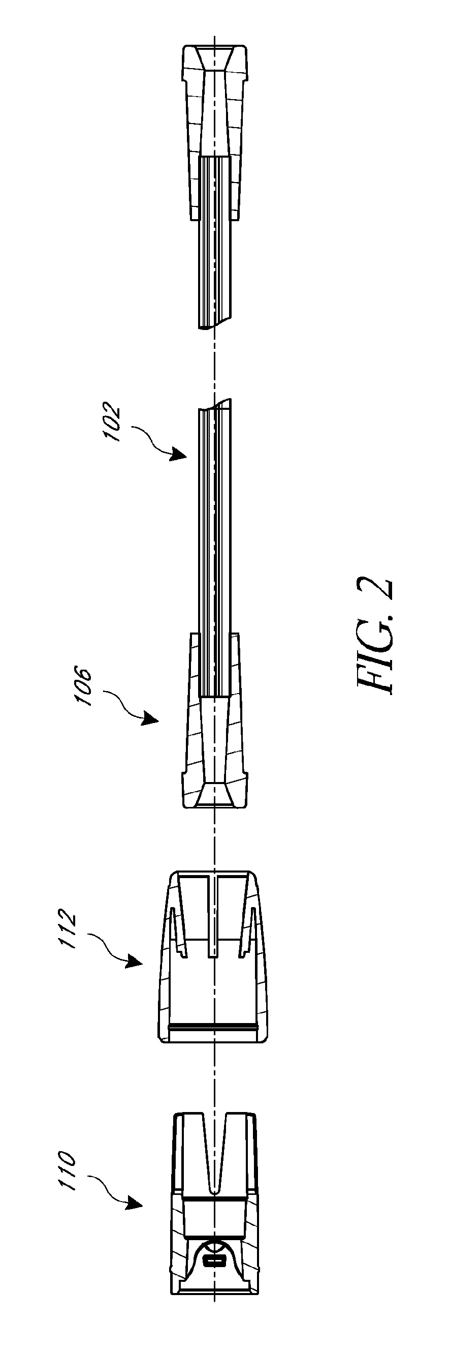
[0025]With reference to FIG. 2, in some configurations, the tubing 102 can include a tubing flange 106 or other end component. The tubing 102 and the tubing flange 106 can be formed from any suitable material. In the illustrated configuration, the two are formed from polyvinyl chloride materials and can be solvent bonded together. While other configurations are possible, forming the tubing 102 and the tubing flange 106 from alike materials facilitates solvent bonding, which results in a very strong and lasting...


PUM


Abstract

A connector and tubing combination includes a tubing segment with an end piece, such as a tubing flange. The tubing flange can be secured within the connector by an outer sleeve and an inner sleeve of the connector. Both of the inner sleeve and the outer sleeve are located outside of the tubing flange and the tubing segment. In addition, the inner sleeve, outer sleeve and the tubing flange are mechanically connected.

Description

FIELD OF THE INVENTION[0001]The present application generally relates to connectors that attach to resilient tubing. More particularly, certain features, aspects and advantages of the present application relate to connectors used to provide an end connection to tubing components.BACKGROUND OF THE INVENTION[0002]Tubing connectors are used to join flexible tubing to various components in the breathing treatment fields. Because the tubing is generally a softer, flexible material and the connector is generally a harder plastic material, these connectors generally are joined to the tubing using adhesives or the like. In situations where the connectors are joined to the tubing without the use of adhesives, it has been found that material creep can loosen the union between the connectors and the tubing over time.SUMMARY OF THE INVENTION[0003]Accordingly, this is a need for a connector to can securely join to an end of tubing.[0004]The connector can be formed such that it is located entirel...

Claims


Application Information

Patent Timeline
IPC IPC(8): A61M16/08F16L23/00F16L37/133
CPCA61M16/0816F16L23/006F16L37/133A61M39/12A61M2207/00
Inventor LAING, BRENT IANSIMS, DAVID JOHNO'CONNOR, MARK THOMAS
Owner FISHER & PAYKEL HEALTHCARE LTD
Why Eureka
Try Eureka