Eureka AIR delivers breakthrough ideas for toughest innovation challenges, trusted by R&D personnel around the world.

Method and device for operating a fuel injection device, especially of a motor vehicle

a fuel injection device and motor vehicle technology, applied in the direction of electric control, combustion engines, machines/engines, etc., can solve the problems of not ensuring the balance of the quantity of fuel flowing into and out of the mentioned high-pressure reservoir, and the quantity (or mass) of fuel actually supplied to the high-pressure reservoir is not. , to achieve the effect of minimizing false reports of balance disturbance and improving recognition quality

Inactive Publication Date: 2016-01-07
ROBERT BOSCH GMBH
View PDF4 Cites 2 Cited by
  • Summary
  • Abstract
  • Description
  • Claims
  • Application Information

AI Technical Summary

Benefits of technology

The invention relates to a system that recognizes when there is a balance disturbance in the operation of an internal combustion engine and takes appropriate action to repair it. This is done by detecting a deviation in the pressure of the fuel in the engine and calculating the amount of fuel needed based on the desired torque and engine temperature. By adjusting the amount of fuel injected, the system can compensate for the balance disturbance and prevent the engine from shutting down. The invention is simple and cost-effective to implement.

Problems solved by technology

In operation of such an injection device, it may happen that owing to a malfunction the quantity (or mass) of fuel actually supplied to the high-pressure reservoir is not equal to the quantity envisaged for fuel injection and required for the pressure regulation.
In driving operation of a motor vehicle having such an internal combustion engine, the situation may therefore arise that properties or modes of behavior predicted for mentioned components are not maintained and, as a result, the mentioned balance of quantities of fuel flowing into and out of the mentioned high-pressure reservoir is no longer ensured.

Method used


Image

  • Method and device for operating a fuel injection device, especially of a motor vehicle
  • Method and device for operating a fuel injection device, especially of a motor vehicle
  • Method and device for operating a fuel injection device, especially of a motor vehicle

Examples


Embodiment Construction

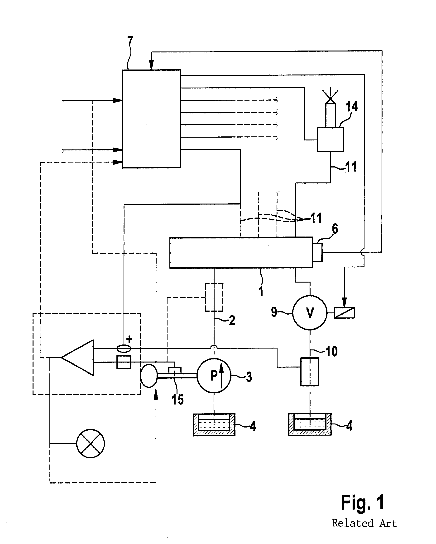
[0033]FIG. 1 shows a high-pressure fuel reservoir 1 which, via a feed line 2 from a fuel pump 3 which sucks fuel out of a fuel vessel 4, is supplied with fuel that has been brought to a high injection pressure. In this case, pressures substantially above 1000 bar occur. The pressure in the high-pressure fuel reservoir is detected by a pressure transducer 6 the signal of which is supplied to a control device 7 with which a pressure control valve 9 is actuated by a corresponding signal when a fixed pressure or a desired pressure, which may be dependent on a respective operating state of the associated internal combustion engine, is exceeded. Pressure control valve 9 is situated in a fuel return line 10 from high-pressure fuel reservoir 1 to fuel vessel 4.

[0034]Also leading from high-pressure fuel reservoir 1 are pressure lines 11 which are each connected to a fuel injection valve 14 via which a desired quantity of fuel in each case may be injected into the internal combustion engine a...


PUM


Abstract

In a method for operating a fuel injection device of a motor vehicle, fuel is conveyed under high pressure into a high-pressure reservoir, the pressure of which is controlled with the aid of a pressure regulation and from which fuel is taken for injection via at least one fuel injection valve under the control of a control device. A control pressure deviation of the pressure in the high-pressure reservoir is detected and the existence of a balance disturbance between quantity of fuel supplied to the high-pressure reservoir and quantity of fuel taken from the high-pressure reservoir is deduced from the control pressure deviation. If a balance disturbance exists, operational influencing of the fuel injection device counteracting the balance disturbance is produced and / or a corresponding report is generated.

Description

BACKGROUND OF THE INVENTION[0001]1. Field of the Invention[0002]The present invention relates to a method and a device for operating a fuel injection device of a motor vehicle, and a computer program that executes all steps of the method according to the present invention.[0003]2. Description of the Related Art[0004]A fuel injection device is known from published German Patent Application document DE 196 25 487 A1. In the case of that device, fuel is conveyed under high pressure into a high-pressure reservoir (in the case of a self-ignition internal combustion engine the so-called “common rail”) the pressure of which is controlled by a pressure regulator disposed in a control unit or by a corresponding pressure control valve and from which fuel is taken for injection via electrically controlled injection valves.[0005]In operation of such an injection device, it may happen that owing to a malfunction the quantity (or mass) of fuel actually supplied to the high-pressure reservoir is n...

Claims


Application Information

Patent Timeline
Patent Type & Authority Applications(United States)
IPC IPC(8): F02D41/38
CPCF02D41/3863F02D41/3836F02D19/0623F02D41/0025F02D2041/224F02D2041/227F02D2041/228F02D2250/26Y02T10/30
Inventor MUENNICH, CHRISTIAN ALEXANDERZEIDLER, JOHANNESWOKOECK, TILLBECKER, THOMAS
Owner ROBERT BOSCH GMBH
Why Eureka
Eureka Blog
Learn More