

Terminal fitting and method of manufacturing wire with terminal
a technology of terminals and fittings, applied in the direction of contact member manufacturing, coupling device connection, connection contact member material, etc., can solve the problems of deterioration of efficiency, increased labor and time of crimping process, and varied troubles, so as to improve the working efficiency of crimping process and prevent failure of connection with wires
- Summary
- Abstract
- Description
- Claims
- Application Information
AI Technical Summary
Benefits of technology
Problems solved by technology
Method used
Image

Examples
first embodiment
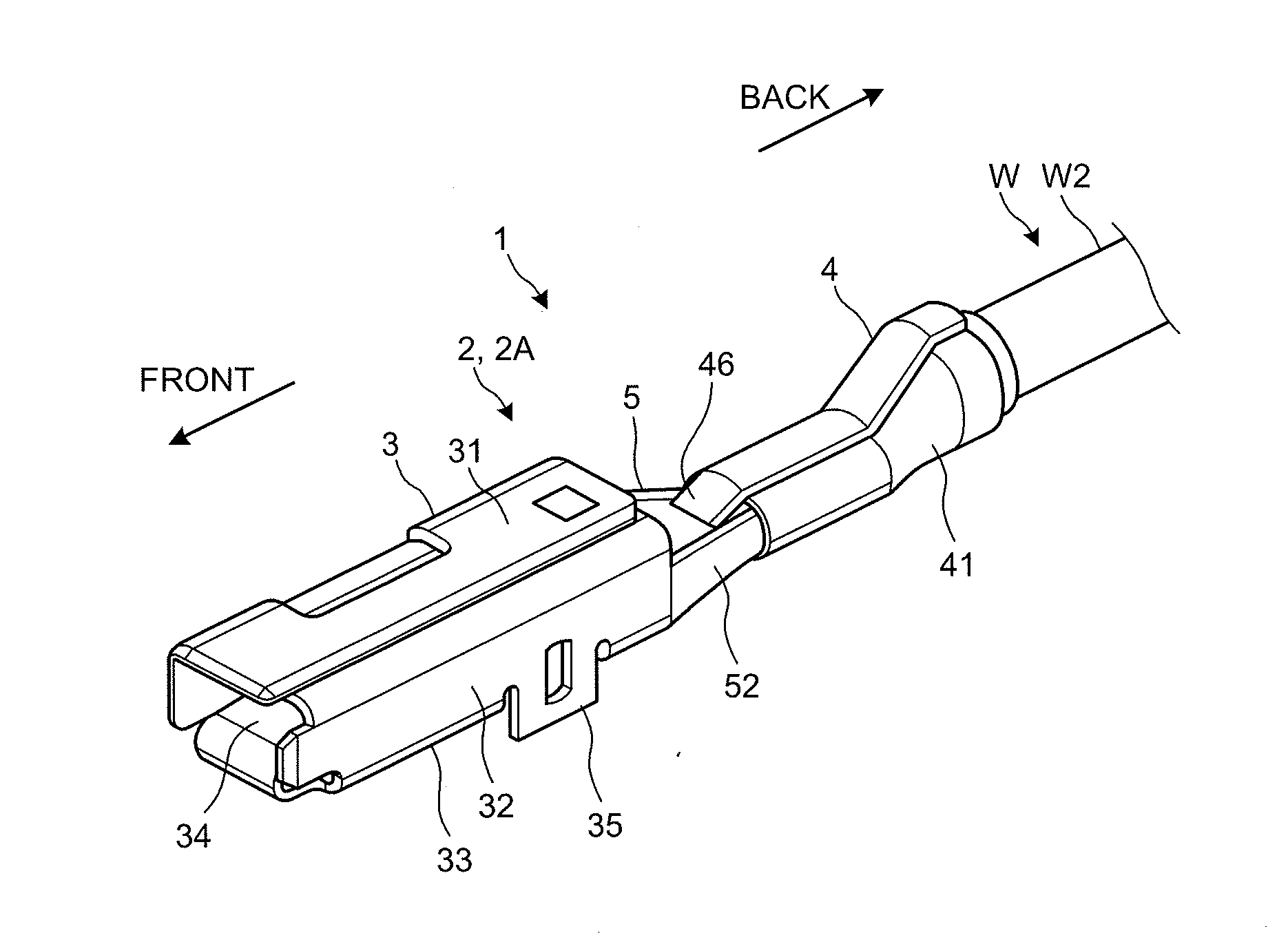
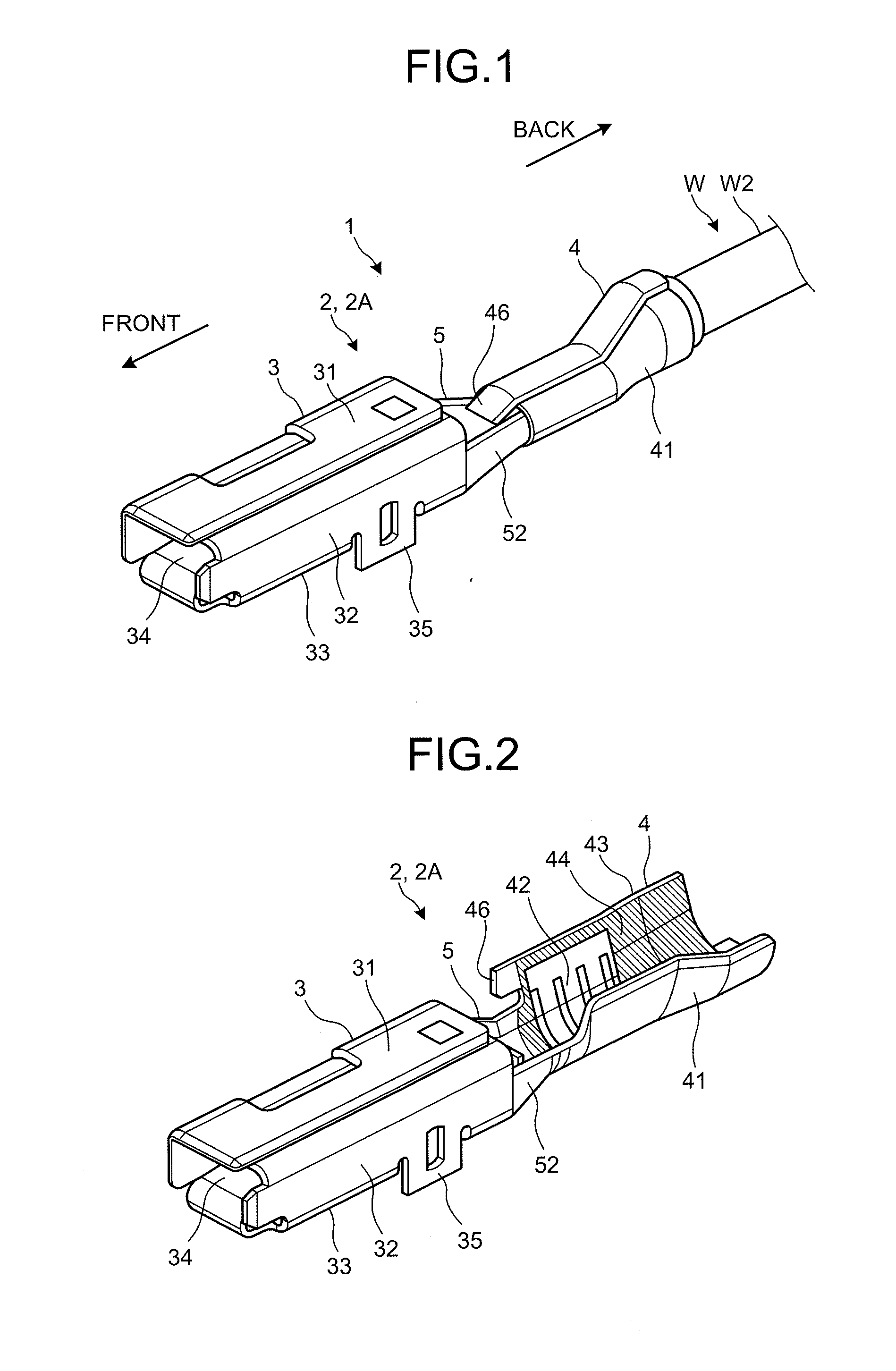
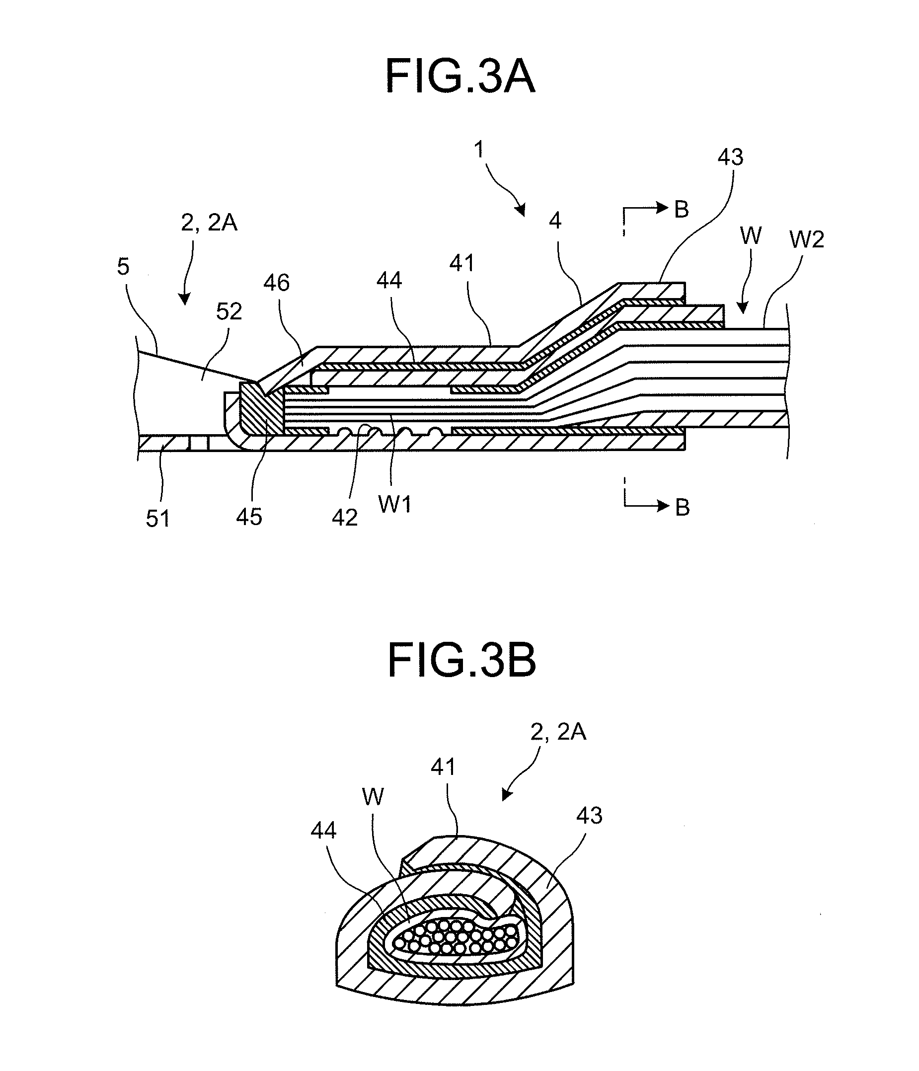
[0046]Next, the terminal fitting 2A according to a first embodiment will be described in detail with reference to FIGS. 1 to 5. The wire connection part 4 in the terminal fitting 2A is provided with a projecting piece 46 projecting forward (toward the electric contact part 3) from the vicinity of one edge of the U-shaped barrel piece 41 as illustrated in FIG. 2. As illustrated in FIGS. 1 and 3, the projecting piece 46 is caulked simultaneous with the caulking of the barrel piece 41 or after the barrel piece 41 is caulked. The projecting piece 46 is thus deformed toward the core W1 of the wire W to be in contact with the tip end of the core W1. More specifically, the projecting piece 46 has a function as a positioning unit to position the wire W in the longitudinal direction by contacting to the tip end of the core W1. In other words, the positioning unit is formed by deforming the projecting piece 46, which projects forward at the circumferential end of the barrel piece 41, toward t...
second embodiment
[0049]Next, a terminal fitting 2B according to a second embodiment will be described in detail with reference to FIGS. 6 to 10. A wire connection part 4 in the terminal fitting 2B is provided with a projecting piece 47 projecting forward (toward the electric contact part 3) from the vicinity of one edge of a water stop part 44 formed on a U-shaped barrel piece 41 as illustrated in FIG. 7. As illustrated in FIGS. 6 and 8, the projecting piece 47 is caulked simultaneous with the caulking of the barrel piece 41 or after the barrel piece 41 is caulked. The projecting piece 47 is thus deformed toward a core W1 of a wire W to be in contact with the tip end of the core W1. More specifically, the projecting piece 47 has a function as a positioning unit to position the wire W in the longitudinal direction by contacting to the tip end of the core W1. In other words, the positioning unit is formed by deforming the projecting piece 47, which projects forward at the circumferential end of the wa...
third embodiment
[0053]Next, a terminal fitting 2C according to a third embodiment will be described in detail with reference to FIGS. 11 to 14. In the state in which a barrel piece 41 is crimped to a wire W by caulking, a small-diameter part 48, which is deformed toward a core W1 of the wire W by caulking, is formed at a front end of the barrel piece 41 of a wire connection part 4 in the terminal fitting 2C as illustrated in FIGS. 11 and 13. The small-diameter part 48 is configured to be in contact with the tip end of the core W1. More specifically, the small-diameter part 48 has a function as a positioning unit to position the wire W in the longitudinal direction by contacting to the tip end of the core W1. In other words, the positioning unit is formed by deforming the small-diameter part 48 at the front end of the barrel piece 41 toward the core W1 by caulking. The small-diameter part 48 is formed anterior to a serration part 42 for positioning the tip end of the core W1. As illustrated in FIG. ...
PUM
 Abstract
Description
Claims
Application Information