Electrical machine

Active Publication Date: 2016-01-07
SPAL AUTOMOTIVE
View PDF0 Cites 10 Cited by
  • Summary
  • Abstract
  • Description
  • Claims
  • Application Information

AI Technical Summary

Benefits of technology

[0015]In this context the primary technical purpose of the present invention is to provide a rotary electrical machine which disperses the heat generated internally

Problems solved by technology

One of the principle difficulties of the sealed type of electrical machine is the dispersal of the heat generated by the electronic module during operation of the electrical machine.
However, despite the relatively low internal resistance of the electronic power components, especi

Method used


Image

  • Electrical machine
  • Electrical machine
  • Electrical machine

Examples


Example

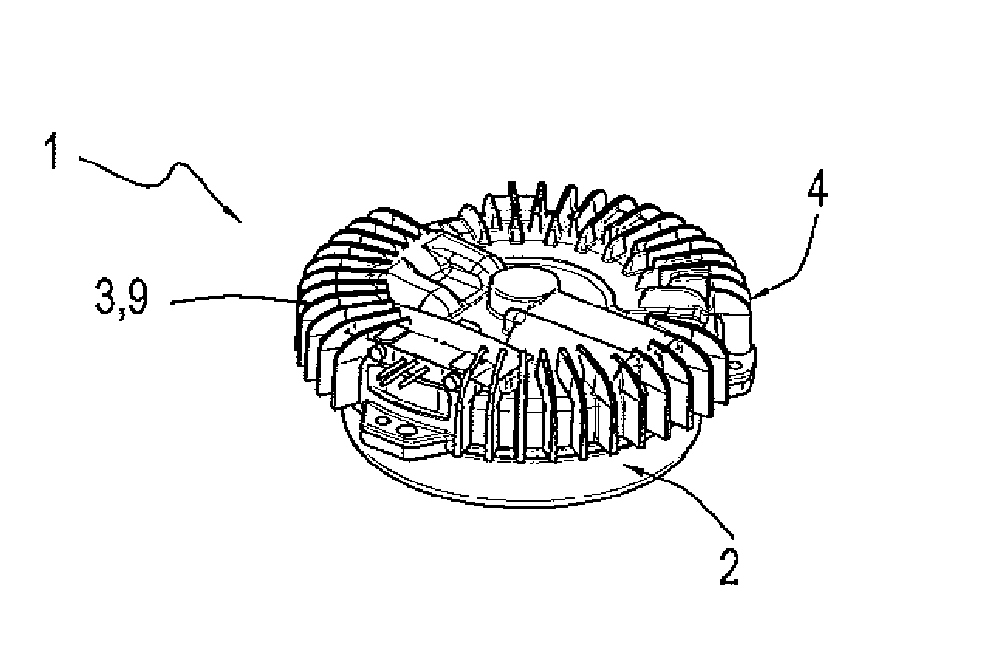
[0028]With reference to the accompanying drawings, the numeral 1 indicates a rotary electrical machine according to the present invention.

[0029]The machine 1 in the preferred embodiment is an electric motor of the sealed type, that is, without any openings for access to the inside, to which express reference will hereinafter be made but without thereby limiting the scope of the invention.

[0030]The electrical machine 1 will be described in detail solely for the parts necessary for the understanding of this invention.

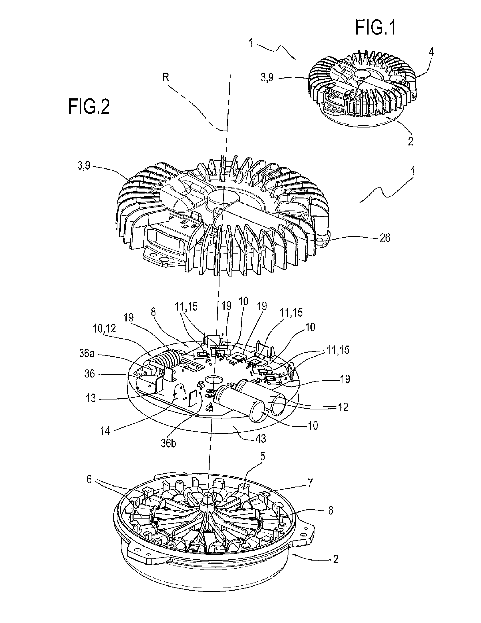
[0031]The machine 1 comprises a casing 2 and a cap 3 for closing the casing 2 to form, with the casing 2, a case or closed container 4.

[0032]The electrical machine 1 comprises a stator 5 fixed to the casing 2 and comprising an electrical winding 6 and a rotor 7 inserted in the case 4 and attached to the case in a rotary manner.

[0033]The machine 1 has its own axis of rotation R around which the rotor 7 rotates.

[0034]An example of the stator 5 is described in the patent EP2...


PUM


Abstract

A rotary electrical machine incorporating an electronic module that includes a printed circuit mounted with a plurality of surface mounted electronic components and a plurality of pin-through-hole electronic components; the electrical machine includes a dissipator for dispersing the heat generated by the electronic module; the surface mounted electronic components and the pin-through-hole electronic components are mounted between the printed circuit and the dissipator; the electronic module also includes a transferring element, also mounted between the printed circuit and the dissipator, in thermal contact with at least one of the surface mounted electronic components; the transferring element is designed to disperse the heat generated by the surface mounted electronic components towards the dissipator with the aid of a thermally conductive and electrically isolating filler material inserted between the transferring element and the dissipator.

Description

TECHNICAL FIELD[0001]This invention relates to a rotary electrical machine and a method for its assembly with reference in particular to the integrated electronic control module.BACKGROUND ART[0002]In general, a rotary electrical machine comprises a casing having inside a stator, rigidly connected to the casing, and a rotor, for example with permanent magnets, rotatably connected to the casing.[0003]An example of a prior art electrical machine used as a reference for the present patent is described in the application WO20133008180 in the name of the same applicant.[0004]An electronic module or electronic control module, connected to the stator, comprising a printed circuit and a plurality of active and passive electronic components forming a power section and a plurality of electronic signal components forming a control section, mounted on the printed circuit.[0005]A cap closes the casing to form a closed container from which connection terminals protrude for the power supply and co...

Claims


Application Information

Patent Timeline
IPC IPC(8): H02K9/22H02K11/00H02K15/00
CPCH02K9/22H02K15/00H02K11/0094H02K5/18H02K11/33H02K9/223
Inventor DE, FILIPPIS, PIETRO
Owner SPAL AUTOMOTIVE
Why Eureka
Try Eureka