
Coherent Frequency-Domain Microwave-Induced ThermoAcoustic Imaging

a microwave-induced thermoacoustic imaging and coherent frequency domain technology, applied in the field of medical imaging devices, methods and systems, can solve the problems that conventional imaging systems often face substantial challenges, and achieve the effects of reducing the required peak rf power level, and improving signal-to-noise (snr) performan

Active Publication Date: 2016-01-14
THE BOARD OF TRUSTEES OF THE LELAND STANFORD JUNIOR UNIV
View PDF8 Cites 5 Cited by
  • Summary
  • Abstract
  • Description
  • Claims
  • Application Information

AI Technical Summary

Benefits of technology

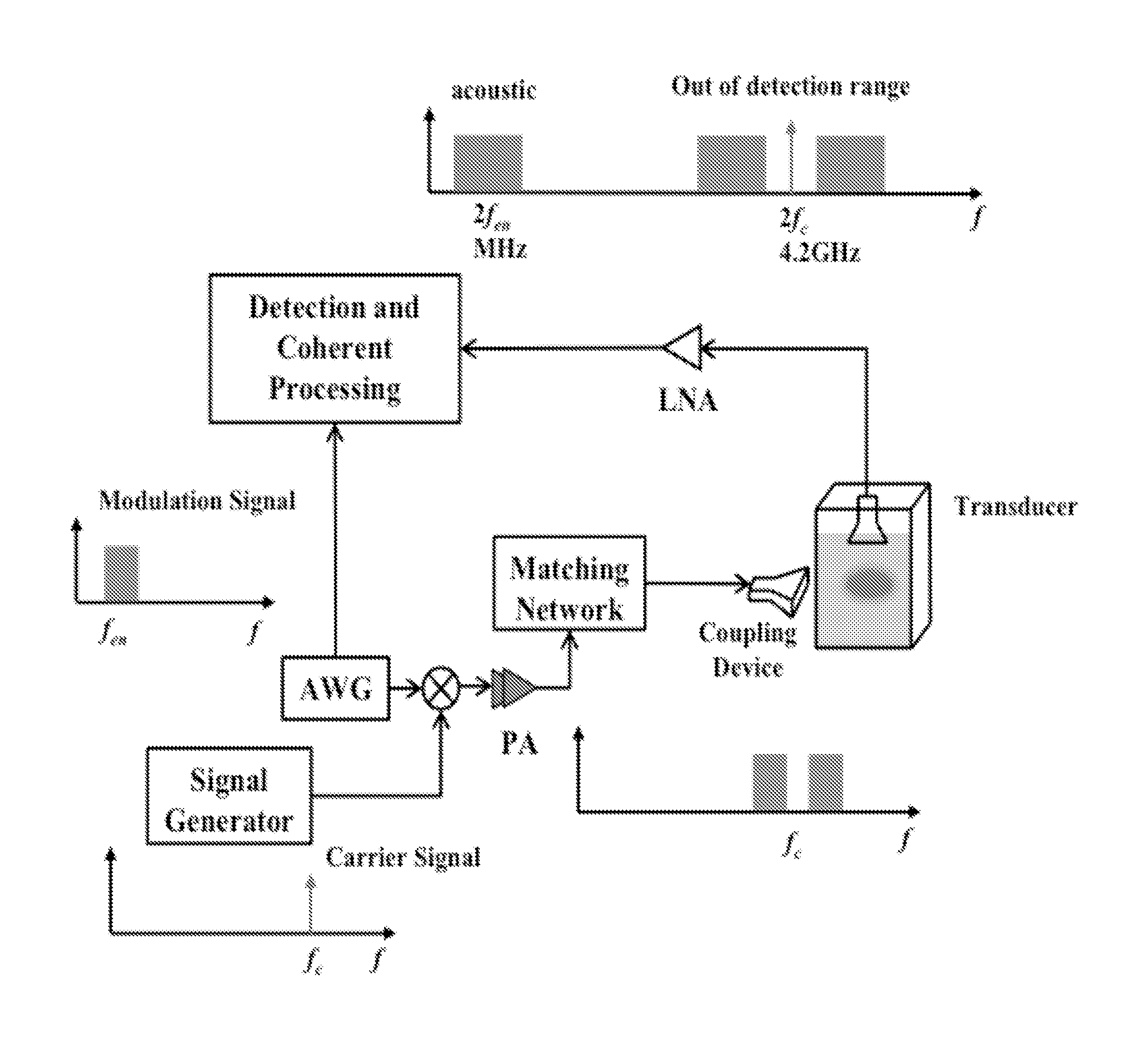
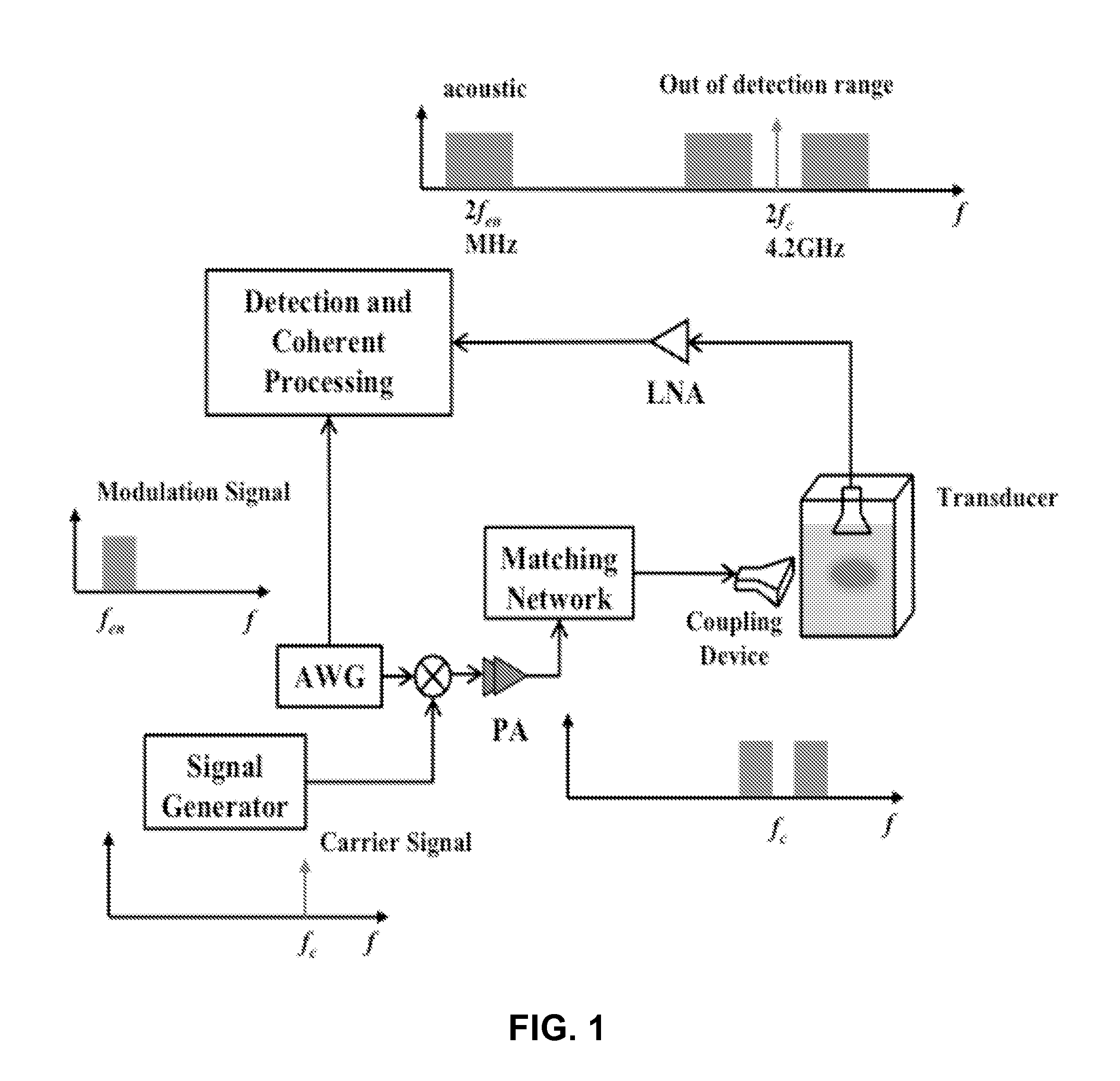
The invention is about improving the signal-to-noise ratio (SNR) of thermoacoustic imaging devices and reducing the required peak power levels from the transmitter. This is achieved by using a filtering device with a cutoff frequency between fm and 2f, which suppresses transmit microwave leakage and feedthrough to the detector. The detected 2f pressure signal passes through the device without filtering. By using double-sideband suppressed-carrier modulation and nonlinear thermoacoustic effect, the generated pressure is separated with microwave leakage and feedthrough in frequency, which enables filtering the latter components by a low-pass filter. This leads to smaller and more efficient devices and systems, opening up the way for handheld and battery operated operation of medical imagers, while also reducing the requirement of peak power. Overall, the invention enables a full solid-state implementation and a portable and handheld thermoacoustic system.

Problems solved by technology

Conventional imaging systems often face substantial challenges in one or more of the following areas: safety (e.g. ionizing radiation), cost, size, and portability of the imaging device (e.g. in the case of MRI or CT scanners).

Method used


Image

  • Coherent Frequency-Domain Microwave-Induced ThermoAcoustic Imaging
  • Coherent Frequency-Domain Microwave-Induced ThermoAcoustic Imaging
  • Coherent Frequency-Domain Microwave-Induced ThermoAcoustic Imaging

Examples


Embodiment Construction

[0030]The thermoacoustic (TA) effect was first demonstrated by using a pulse light source incident on a sample to generate acoustic waves. Using microwave (MW) excitation, the microwave-induced thermoacoustic technique combines the contrast of microwave imaging, which is based on dielectric properties of different materials, with the high resolution of ultrasound (US) detection. It has the potential to achieve penetration depth in excess of 5 cm even in dispersive tissue. With this technique, the target tissue generates stress wave due to thermal expansion after the absorption of the microwave energy. Photoacoustic imaging, which employs laser as the excitation source, shares the same physical principles. However, it is only suitable for superficial applications because of the limited penetration depth.

[0031]Conventional microwave-induced thermoacoustic uses a high power source to generate a short pulse. The stress confinement condition limits the maximum pulse width. To achieve the...


PUM


Abstract

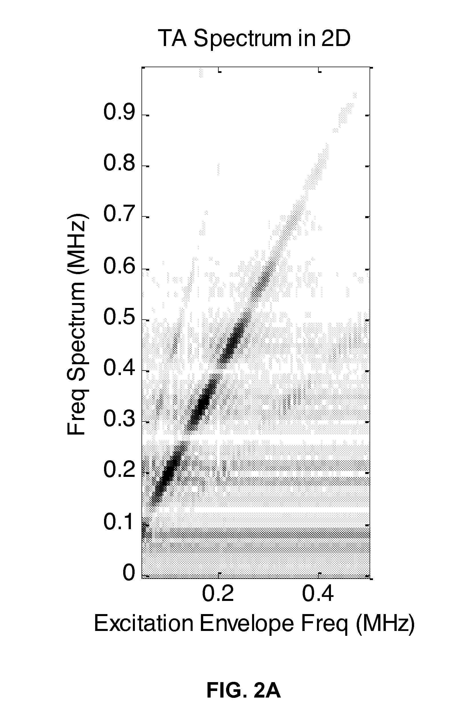
A thermoacoustic imaging device is provided having a transmitter configured to provide an electromagnetic transmit signal (e.g. a continuous sinusoidal signal) to an object being imaged. The transmit signal is a modulated continuous-wave signal based on a carrier frequency signal fc modulated at a modulation frequency at or near fm. The detector is further configured to receive an acoustic signal from the object being imaged, and is responsive to acoustic frequencies at or near 2fm. A non-linear thermoacoustic effect in the object being imaged generates the acoustic signal from the object being imaged. Spectroscopic maps could be generated and imaged object could be analyzed. The device enhances signal-to-noise ratio of the reconstructed image and reduces the requirement of peak power in thermoacoustic imaging systems. In addition, the generated pressure of the imaged object is separated from microwave leakage and feedthrough in frequency through the nonlinear thermoacoustic effect.

Description

CROSS-REFERENCE TO RELATED APPLICATIONS[0001]This application claims priority from U.S. Provisional Patent Application 61 / 947,259 filed Mar. 3, 2014, which is incorporated herein by reference.STATEMENT OF GOVERNMENT SPONSORED SUPPORT[0002]This invention was made with Government support under contract no. HR0011-13-C-0060 awarded by the Defense Advanced Research Projects Agency. The Government has certain rights in the invention.FIELD OF THE INVENTION[0003]The invention relates to medical imaging devices, methods and systems.BACKGROUND OF THE INVENTION[0004]The majority of the common imaging modalities currently used for diagnosis and screening rely on physical interaction concepts developed over 30 years ago. Conventional imaging systems often face substantial challenges in one or more of the following areas: safety (e.g. ionizing radiation), cost, size, and portability of the imaging device (e.g. in the case of MRI or CT scanners). In addition to addressing these concerns, a new im...

Claims


Application Information

Patent Timeline
IPC IPC(8): A61B5/00
CPCA61B2576/00A61B5/0093A61B8/48
Inventor ARBABIAN, MOHAMMAD AMINNAN, HAO
Owner THE BOARD OF TRUSTEES OF THE LELAND STANFORD JUNIOR UNIV
Learn More