
Peritoneal Dialysis System and Method

a dialysate and peritoneal technology, applied in the field of peritoneal dialysis, can solve the problems of heavy bags of dialysate, patients' dislike of having to transport, handle and set up the floppy, and expensive dialysate providers to manufactur

Inactive Publication Date: 2016-01-14
HOFFMAN JOSEF C A
View PDF7 Cites 11 Cited by
  • Summary
  • Abstract
  • Description
  • Claims
  • Application Information

AI Technical Summary

Benefits of technology

The present invention is a machine that generates and uses warm, sterile peritoneal dialysate for patients with kidney failure. The machine includes a base, a still, a fluid storage tank, a cassette, a boiling vessel demineralization system, and a tank rinsing system. The machine uses a sterilizing UV lamp and a narrow-band UV light sensor to ensure the quality of the dialysate. The fluid storage tank has a mixer, a cooling water pad, and a heating pad to maintain the dialysate's temperature. The machine automatically demineralizes the boiling vessel and rinses the fluid storage tank each morning. The machine also continuously tracks the number of days remaining until the next required maintenance activity. The technical effects of the invention include improved quality of dialysate, simplified maintenance, and improved patient safety.

Problems solved by technology

There are five inherent disadvantages with the standard Automated Peritoneal Dialysis method.
First, it is very costly for dialysate providers to manufacture up to 18 liters of dialysate per patient per day, and then ship it to each peritoneal dialysis patient's home.
Third, it is impractical for dialysate providers to offer a wide variety of dialysate formulae in order to accommodate each patient's individual blood chemistry.
Fourth, patients dislike having to transport, handle and set up the floppy, heavy bags of dialysate every night.
Finally, a great deal of storage space is required in the patient's home, for bags of fresh dialysate and for the large quantity of trash that is generated when using Automated Peritoneal Dialysis.

Method used


Image

  • Peritoneal Dialysis System and Method
  • Peritoneal Dialysis System and Method
  • Peritoneal Dialysis System and Method

Examples


Embodiment Construction

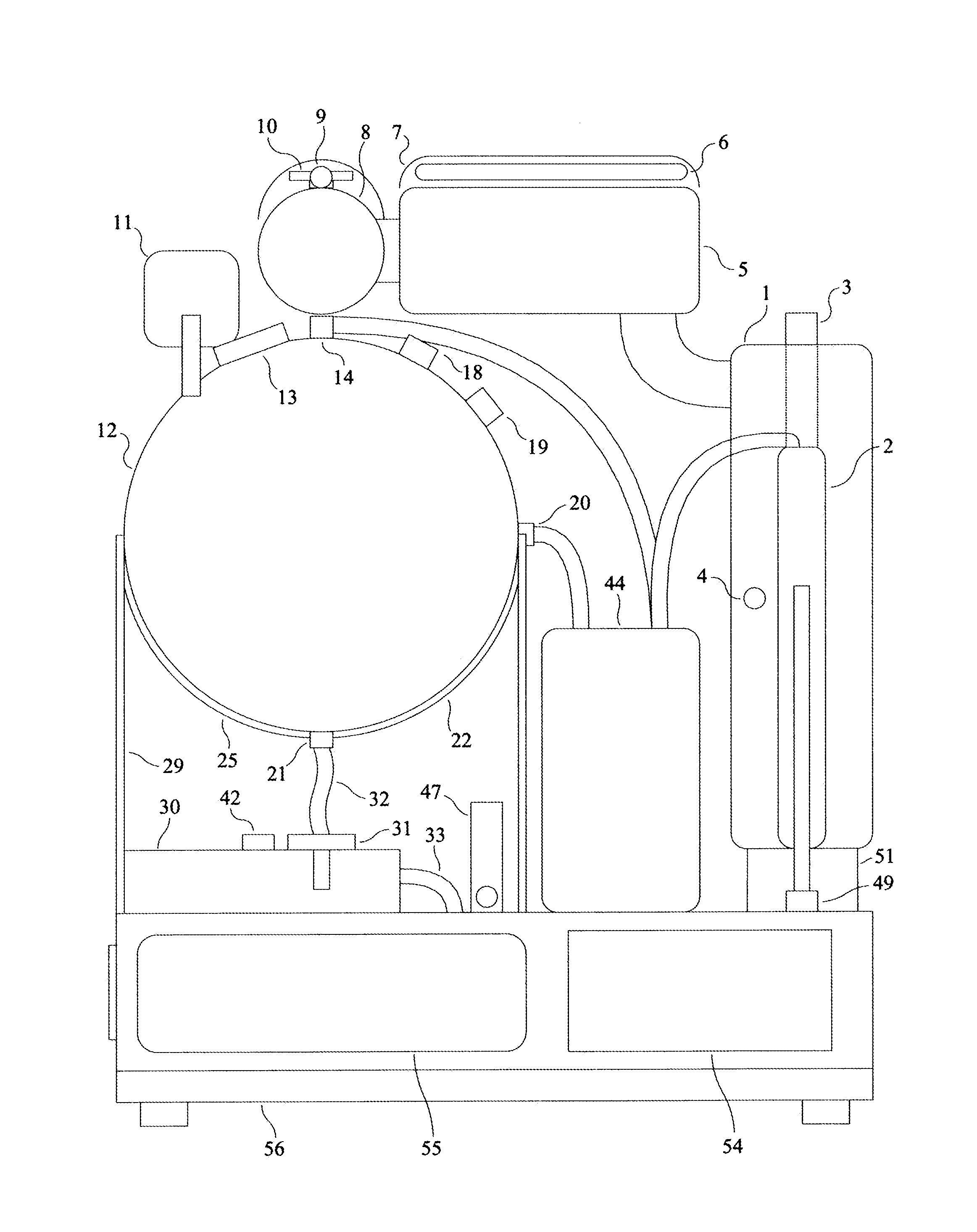
[0024]As seen in FIG. 1, boiling vessel 1 is located at the right rear base 56. It is composed of Pyrex glass, and tap water enters it via constant level tube 2. The boiling vessel might include a temperature insulation jacket. In one embodiment, boiling vessel heating element 3 inserts into the top of the boiling vessel, creating an air tight seal when installed. In an alternate embodiment, the boiling vessel is enclosed in a compact microwave heater. The boiling vessel generates steam during operation, which travels into demister 5. Boiling vessel drain port 50 is located directly below the boiling vessel.

[0025]As seen in FIG. 1, constant level tube 2 is attached to boiling vessel 1. It is composed of Pyrex glass. During operation, tap water flows from condenser 8 to the constant level tube, which maintains a constant water level in boiling vessel 1. Water that does not flow into the boiling vessel, continuously overflows into the constant level tube's spill port. Constant level t...


PUM


Abstract

A peritoneal dialysis machine that includes a base, a boiling vessel, a condenser, a fluid storage vessel, a sterilizing UV lamp, a fluid mixer, a dialysate cassette, a boiling vessel demineralizing system, and an optional fluid storage vessel rinsing system. The peritoneal dialysis machine automatically generates a predetermined volume of distilled water each day. Pre-weighed quantities of low-endotoxin dialysate chemicals are then mixed into the warm distilled water, and the resulting peritoneal dialysate is sterilized via exposure to ultraviolet radiation. These actions are complete by the patient's indicated bed time. The peritoneal dialysis machine then exchanges spent peritoneal dialysate in the user's peritoneal cavity with fresh peritoneal dialysate throughout the night, causing each infusion of fresh dialysate to dwell in the user's peritoneal cavity for a predetermined time. All spent fluids are routed from the peritoneal dialysis machine to a toilet or a sewer drain.

Description

FIELD OF THE INVENTION[0001]The present invention relates to the generation of peritoneal dialysate, and to conducting peritoneal dialysis. The peritoneal dialysis machine of the present invention is particularly suitable for use in the patient's home, or in a nursing home.BACKGROUND OF THE INVENTION[0002]The current world standard for peritoneal dialysis is Automated Peritoneal Dialysis (APD), wherein an automated cycler exchanges spent dialysate in the patient's peritoneal cavity with fresh dialysate, allowing the fresh dialysate to dwell in the peritoneal cavity for a predetermined period between each exchange. An end-stage renal patient will typically receive three to six dialysate exchanges per day, seven days a week. This method of APD has changed little in the past 30 years.[0003]There are many U.S. patents associated with peritoneal dialysis, and the large majority of these patents are associated with a machine or a process that exchanges spent dialysate in the patient's per...

Claims


Application Information

Patent Timeline
Patent Type & Authority Applications(United States)
IPC IPC(8): A61M1/28A61M1/32
CPCA61M1/287A61M1/32A61M1/28A61M1/288A61M2205/3653A61M1/155A61M1/1565A61M1/154A61M1/159A61M1/1524A61M1/1563
Inventor HOFFMAN, JOSEF, C., A.
Owner HOFFMAN JOSEF C A
Learn More