
Cell concentration devices and methods

a cell concentration and cell technology, applied in the field of regenerative medicine, can solve the problems of not being able to achieve high yield and high final concentration, and many commercial devices are not able to consistently capture high percentages of nucleated cells, so as to facilitate the extraction of target cells, reduce cross-sectional area, and increase the thickness of the layer of interest

Active Publication Date: 2016-01-14
CERVOS MEDICAL LLC
View PDF5 Cites 9 Cited by
  • Summary
  • Abstract
  • Description
  • Claims
  • Application Information

AI Technical Summary

Benefits of technology

The invention is about a new device for collecting cells from marrow or other tissue. Unlike other devices that form a closed space to capture cells, this device allows the fluid containing the cells to flow naturally through it. The device has a channel that allows the fluid to flow freely without interfering with the natural separation of different density components. This design also helps to collect a high yield and concentration of specific target cells.

Problems solved by technology

The challenge for any apparatus designed to accomplish such a task is the ability to volume reduce the fluid in which the nucleated cells are suspended while recovering as many cells as possible.
Many commercial devices are not able to consistently capture high percentages of nucleated cells while at the same time efficiently volume reduce (i.e., concentrate) the beginning fluid.
In other words, many devices are not able to simultaneously obtain a high yield and a high final concentration.

Method used


Image

  • Cell concentration devices and methods
  • Cell concentration devices and methods
  • Cell concentration devices and methods

Examples


Embodiment Construction

[0044]A description of example embodiments of the invention follows.

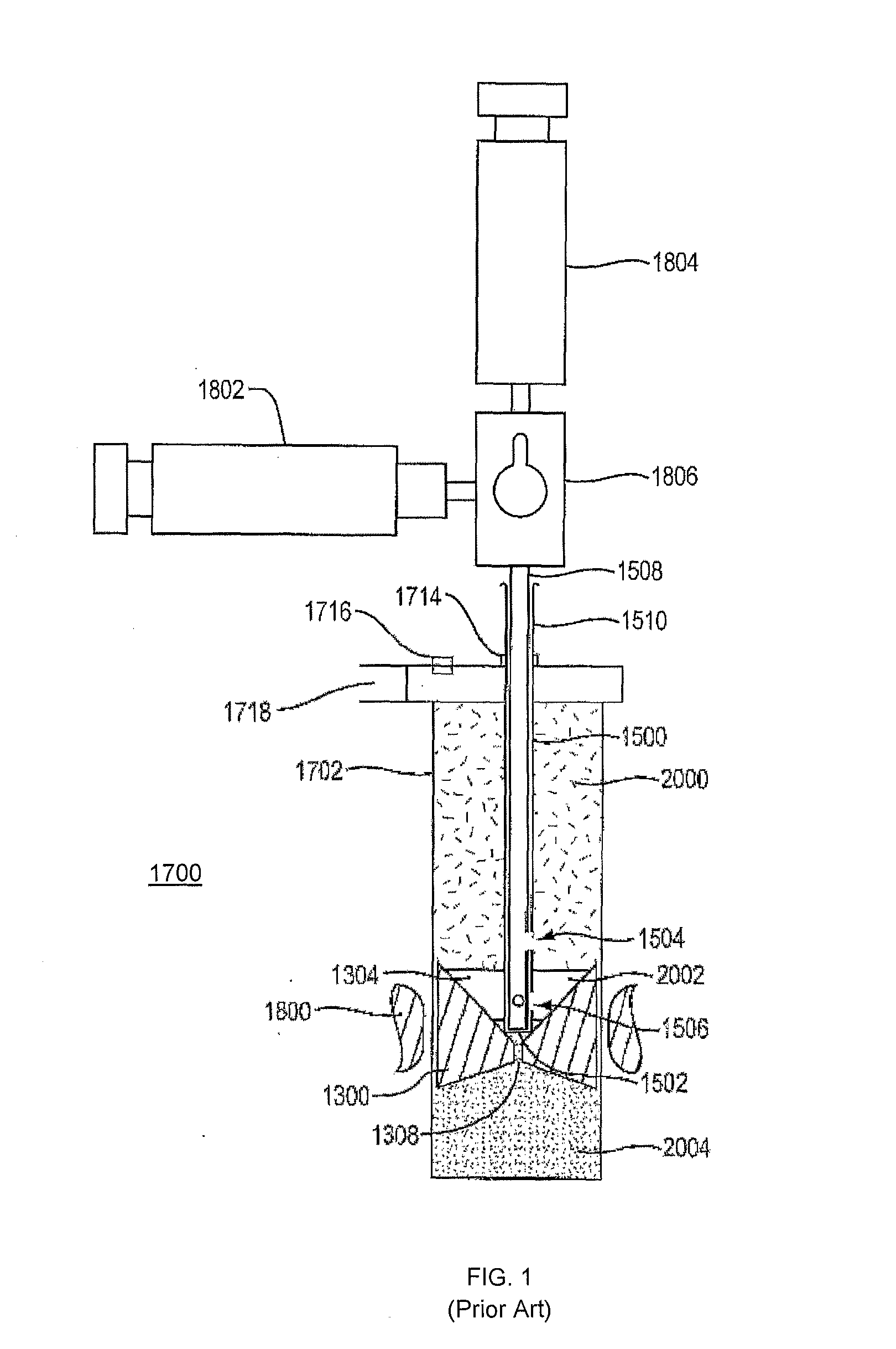
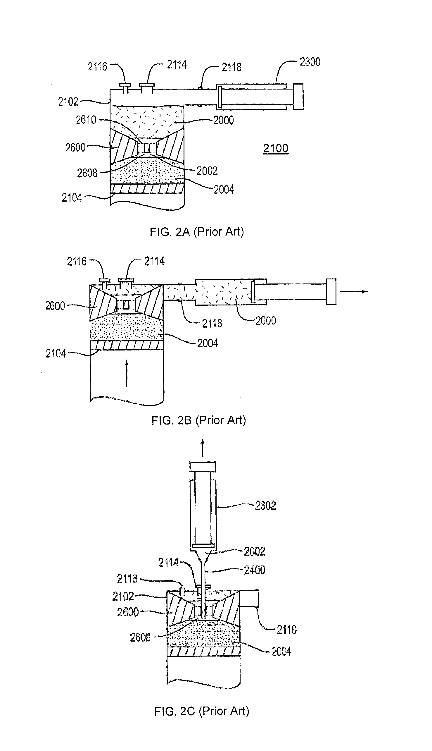
[0045]A prior version of a system for concentrating and separating cells (also referred to herein as a cell concentrator) has been described in International Application No. PCT / US2010 / 036696, published on Dec. 2, 2010 as WO2010 / 138895, incorporated herein by reference in its entirety. Here, an improved system is described that has been fabricated and tested. Some key features of the improved system include:

[0046]a) a locking base;

[0047]b) a double needle extraction system with jet flushing;

[0048]c) an extraction needle lock that forces needle to seat in float; and

[0049]d) a syringe lock-out tab to ensure proper order of extraction.

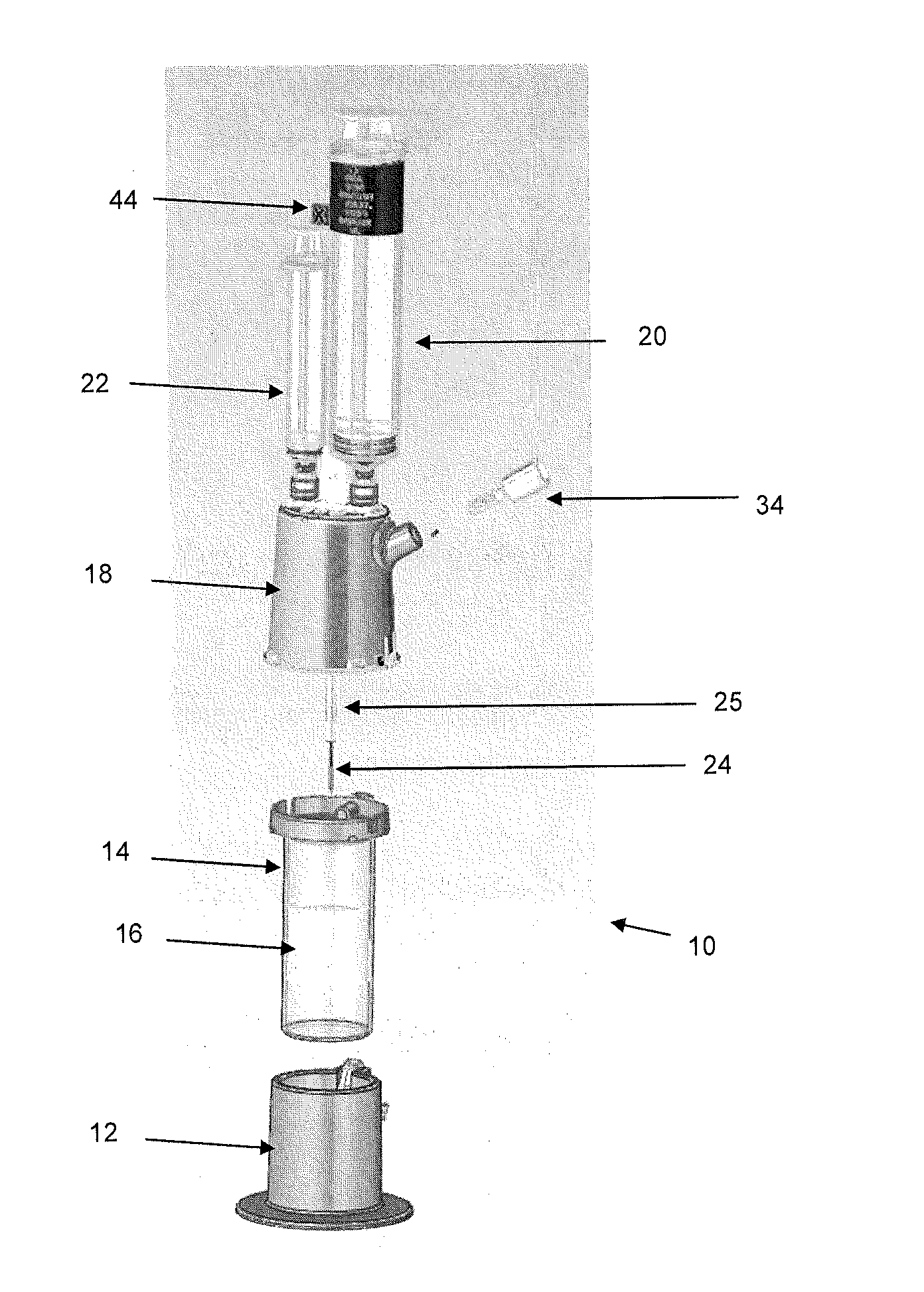
[0050]FIG. 3 is an exploded view of an improved system 10 for separating components of difference densities from a physiological fluid according to an example embodiment of the invention. System 10 includes a base 12, a separation vial (container) 14, a float (insert) 16 disposed in the v...


PUM

PropertyMeasurementUnit
Fractionaaaaaaaaaa
Fractionaaaaaaaaaa
Angleaaaaaaaaaa

Abstract

A system and associated method for concentrating and separating components of different densities from fluid containing cells using a centrifuge includes a container defining a cavity for receiving the fluid. The container has a top, a sidewall extending from the top, and a bottom disposed opposite the top and in sealing engagement with the sidewall. An insert is slidably disposed in the cavity of the container and defines a lumen through the insert. The lumen, which includes a hole and a funnel-shaped upper portion in fluid communication with the hole, forms an open fluid path between opposite ends of the insert. The insert has a density such that upon centrifugation a selected component of the fluid resides within the lumen. A container port is disposed in the top of the container to transfer the fluid into the container and to withdraw a fluid component other than the selected component from the container. The system includes a manifold that includes a manifold port, a vent to vent the container, and a connector to couple to the container port. A cannula is receivable in the manifold port and extendable through the container port into the container and into the lumen of the insert to withdraw the selected component from the lumen.

Description

[0001]This application claims the benefit of U.S. Provisional Application No. 61 / 757,993, filed on Jan. 29, 2013 and U.S. Provisional Application No. 61 / 897,587, filed on Oct. 30, 2013. The entire teachings of the above applications are incorporated herein by reference.BACKGROUND OF THE INVENTION[0002]In the field of regenerative medicine, access to a broad cross section of sub-dermal tissue is typically required to not only source cells but to also deliver therapy. Fluid tissue that is aspirated or otherwise sourced is often separated into one or more components that are present in the fluid tissue, e.g., plasma, red blood cells, fat cells, stem cells or other nucleated cells. Typically, one or more selected components of the fluid tissue are concentrated into a small volume so that the selected components can be used clinically. For example, there are several commercial devices to separate and concentrate nucleated cells from aspirated bone marrow, fat, or cord blood. Some of thes...

Claims


Application Information

Patent Timeline
IPC IPC(8): B01L3/00B01D21/26B01L3/02
CPCB01L3/5082B01D21/262B01L3/0282B01L2200/0689B01L2400/0478B01L2300/046B01L2300/0858B01L2400/0409A61M1/029A61M1/3693B01L3/50215B01L2200/026B01L2200/0684
Inventor LEVINE, ANDY H.MEADE, JOHN C.TISCHLER, NEILCHABOT, JEFFREY R.MCGILLICUDDY, ANDREWDUFFY, JR., NEIL F.
Owner CERVOS MEDICAL LLC
Learn More