Solar relay aircraft powered by ground based solar concentrator mirrors in dual use with power towers

Inactive Publication Date: 2016-01-14
HUNTER JOHN WILLIAM
View PDF37 Cites 32 Cited by
  • Summary
  • Abstract
  • Description
  • Claims
  • Application Information

AI Technical Summary

Benefits of technology

[0031]The Power Towers have the benefit of using all the surplus solar power to energize the grid. Since the CMA is providing dual use solar photons to the Power Towers, a simple receiver can supply electricity to the grid at affordable cost.
[0032]Another use of the solar relay aircraft of the present invention includes an environment equipped with a number of mirror facilities which can direct solar energy onto one or more SRA flying locally, such as flying in a defined pattern adjacent the mirror facility, or between various mirror facilities in a region. The SRA of the present invention may be equipped with instrumentation only, without the added weight of human cargo, and controlled remotely, to further decr

Problems solved by technology

Due to the low intensity of un-concentrated sunlight

Method used


Image

  • Solar relay aircraft powered by ground based solar concentrator mirrors in dual use with power towers
  • Solar relay aircraft powered by ground based solar concentrator mirrors in dual use with power towers
  • Solar relay aircraft powered by ground based solar concentrator mirrors in dual use with power towers

Examples


Embodiment Construction

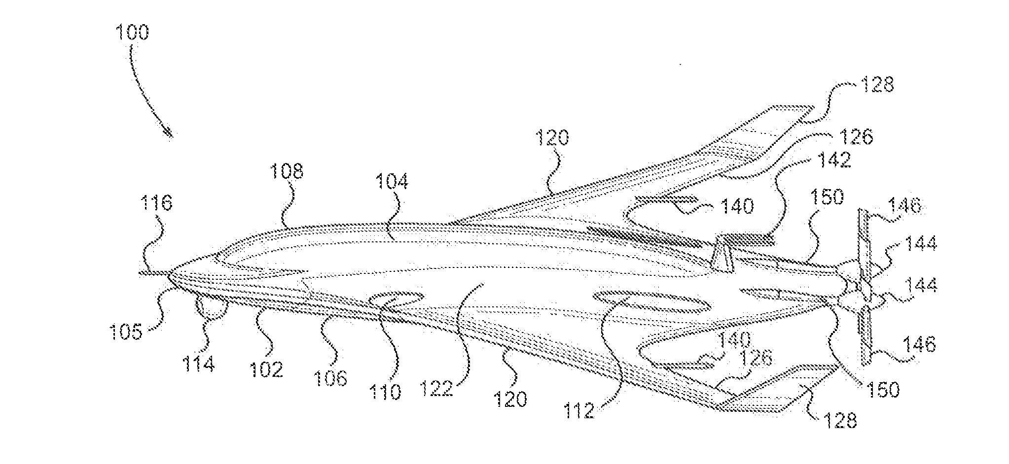
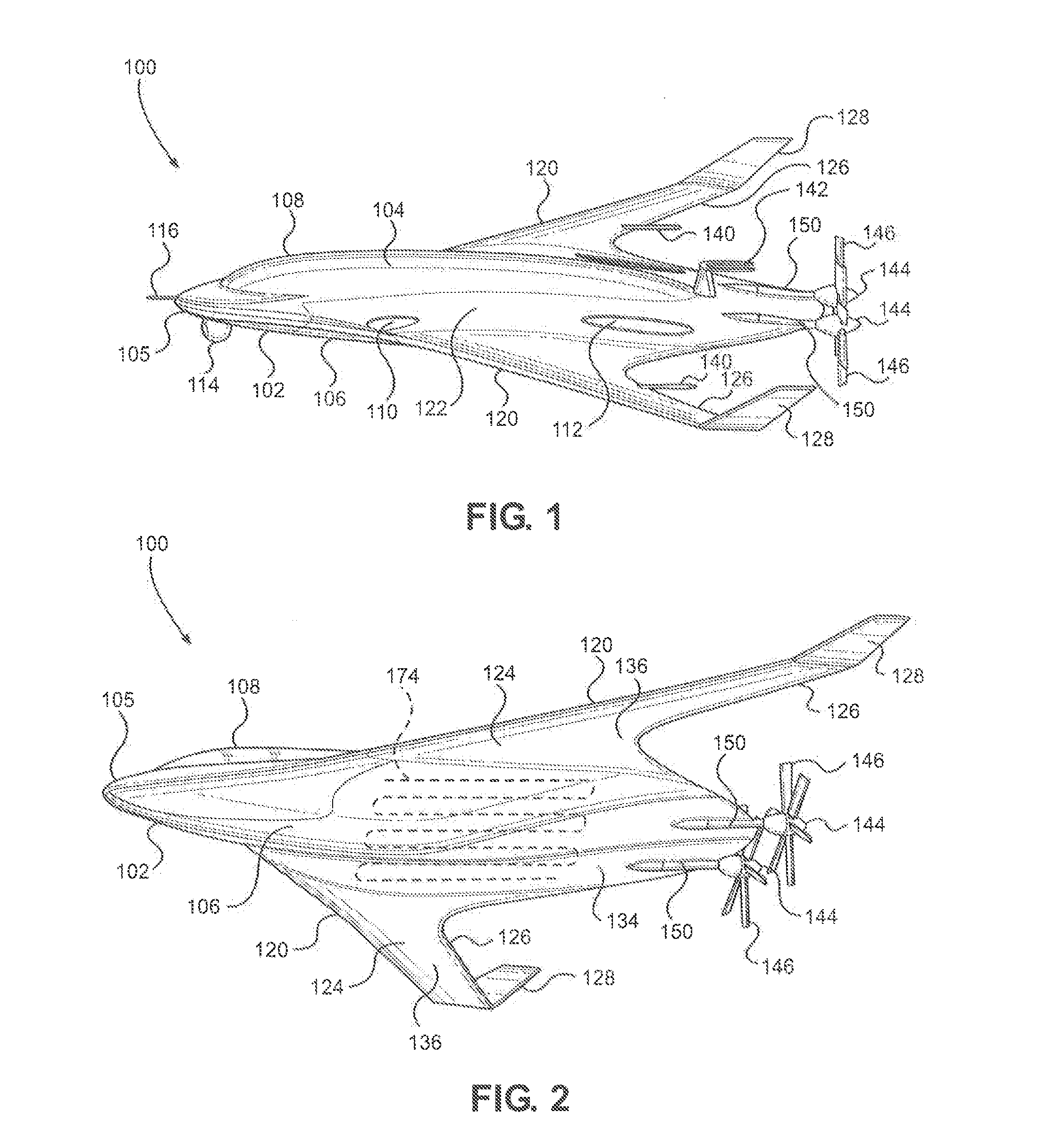
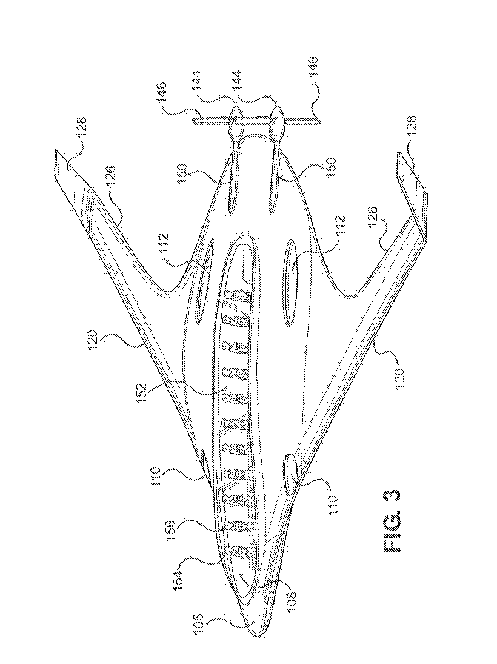
[0063]Referring now to FIG. 1, a top perspective view of a preferred embodiment of the solar relay aircraft (“SRA”) of the present invention is shown and generally designated 100. The SRA 100 uses an elongated Blended Wing Body (BWB) which is a lifting body aircraft with wings 120 blended to a body 102. The body 102 has a shape of an elongated disc, with the elongation in the direction of the flight path, having an upper surface 104 and a lower surface 106. At the front of the body 102 is a nose 105, further elongating the shape of body 102. Each wing 120 is located on either side of the body 102 and extends horizontally outwards. At the end of each wing 120, having an upper surface 122 and a lower surface 124, vertical stabilizers 128 are attached, pointing substantially vertical to improve stability of the SRA 100 while in flight. Attached to the wings 120 are antennas 140. A transponder 116 is attached to the nose 105 at the furthermost tip.

[0064]The upper surface 104 of body 102...


PUM


Abstract

A solar relay aircraft system includes a solar relay aircraft having an upper surface, and a lower surface, and equipped with a solar radiation receiver on said lower surface and capable of converting solar energy to electrical energy. An electric motor in electrical connection with said solar radiation receiver to receive the electrical energy and drives a propeller to propel the solar relay aircraft. A number of ground-based reflector arrays include a plurality of reflecting mirrors for receiving solar radiation from the sun and direct the solar radiation from the sun towards the solar relay aircraft.

Description

RELATED APPLICATIONS[0001]This application is a continuation-in-part and claims the benefit of priority to U.S. patent application Ser. No. 16 / 727,858, filed Aug. 29, 2013 entitled “Solar Relay Aircraft Powered By Ground Based Solar Concentrator Mirrors In Dual Use with Power Towers,” and currently co-pending, which in turn claims benefit of priority to U.S. Provisional Patent Application Ser. No. 61 / 743,227, filed Aug. 29, 2012 entitled “Solar Relay Aircraft Powered By Ground Based Solar Concentrator Mirrors In Dual Use with Power Towers”, and U.S. Provisional Patent Application Ser. No. 61 / 859,728, filed Jul. 29, 2013 entitled Solar Relay Aircraft Powered By Ground Based Mirrors in Dual Use with Power Towers.” Each application referenced above is hereby fully incorporated herein by this reference.FIELD OF THE INVENTION[0002]This invention relates generally to the direction and use of solar energy power. This invention is more particularly, though not exclusively, useful as a solar...

Claims


Application Information

Patent Timeline
IPC IPC(8): B64D27/24B64C39/02
CPCB64D27/24B64C2201/042B64C2201/066B64C39/02B64D27/02B64C2039/105B64D2211/00Y02T50/10Y02T50/50Y02T50/40Y02T50/60Y02T90/40B64U50/19B64U50/34
Inventor HUNTER, JOHN, WILLIAM
Owner HUNTER JOHN WILLIAM
Why Eureka
Try Eureka