
Rocker cover assembly for engines

a technology for engine covers and fasteners, which is applied in the direction of machines/engines, propulsion by batteries/cells, and gearing. it can solve the problems of affecting the reliability of the assembly of the threaded fastener with the cover body and the cover plate, the wear and tear of the threaded bore of the cover body, and the loss of threaded fasteners

Inactive Publication Date: 2016-01-14
ELECTRO-MOTIVE DIESEL
View PDF3 Cites 4 Cited by
  • Summary
  • Abstract
  • Description
  • Claims
  • Application Information

AI Technical Summary

Benefits of technology

The patent discusses a problem where a retaining ring may become misaligned during the assembly of a screw to secure two panels. This can cause the screw to be put into the wrong hole and ultimately affect the overall assembly. The patent aims to solve this issue and ensure a better and more reliable assembly process.

Problems solved by technology

Different material for both of the threaded fastener and the base member may cause wear and tear of the threaded bore of the cover body.
This results in a relatively less reliable assembly of the threaded fastener with the cover body and the cover plate.
In such situations, if the threaded fasteners are neglected and dropped out of sight, the threaded fasteners are likely to be lost, which incurs additional effort in the recovery of the threaded fasteners.
Given a failed recovery attempt, new threaded fasteners are procured, which adds to the burden of cost and effort incurred in the engine's service, and an increased machine downtime.
This results in a faulted assembly of the retained fastener assembly on the pair of panels.

Method used


Image

  • Rocker cover assembly for engines
  • Rocker cover assembly for engines
  • Rocker cover assembly for engines

Examples


Embodiment Construction

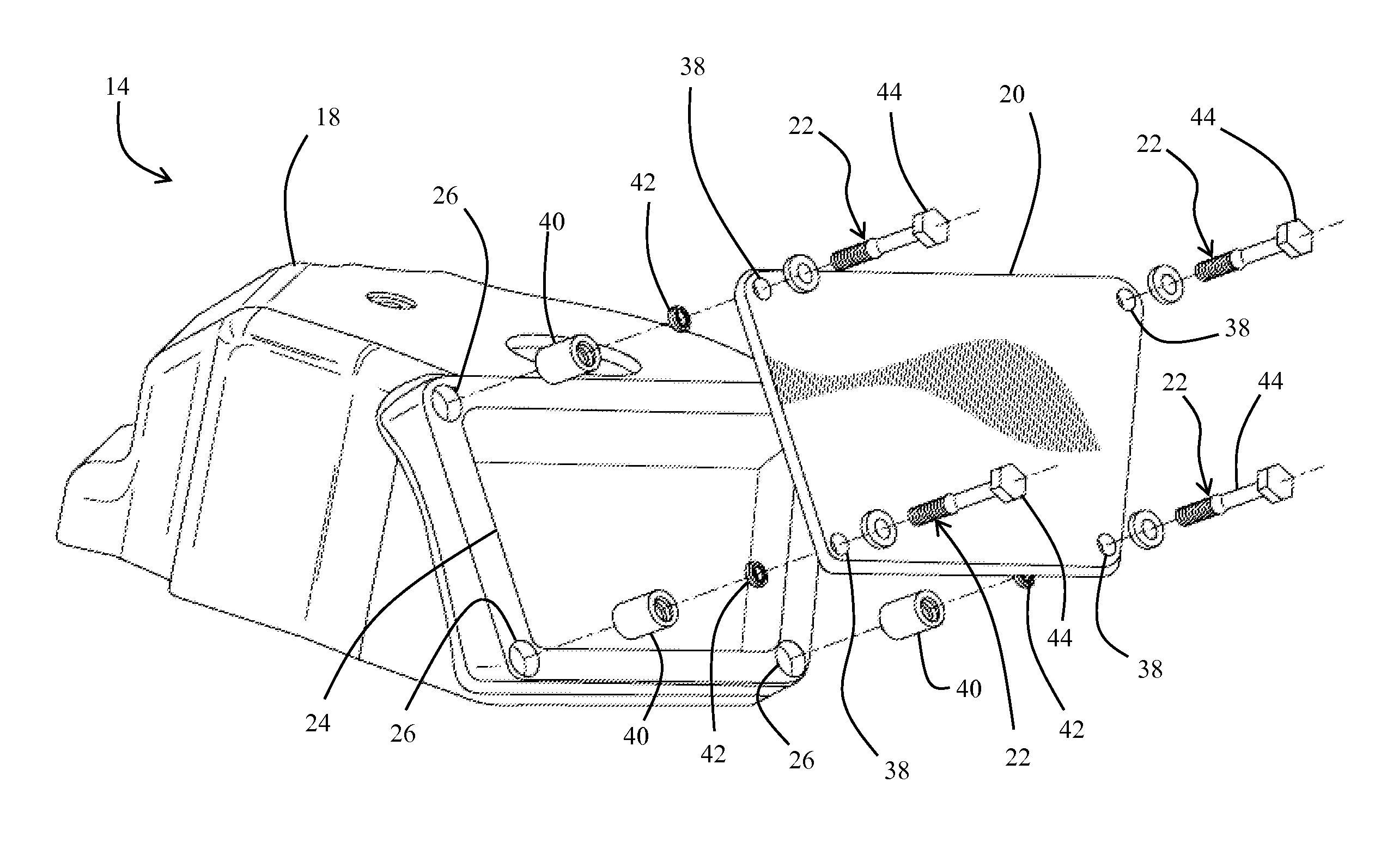
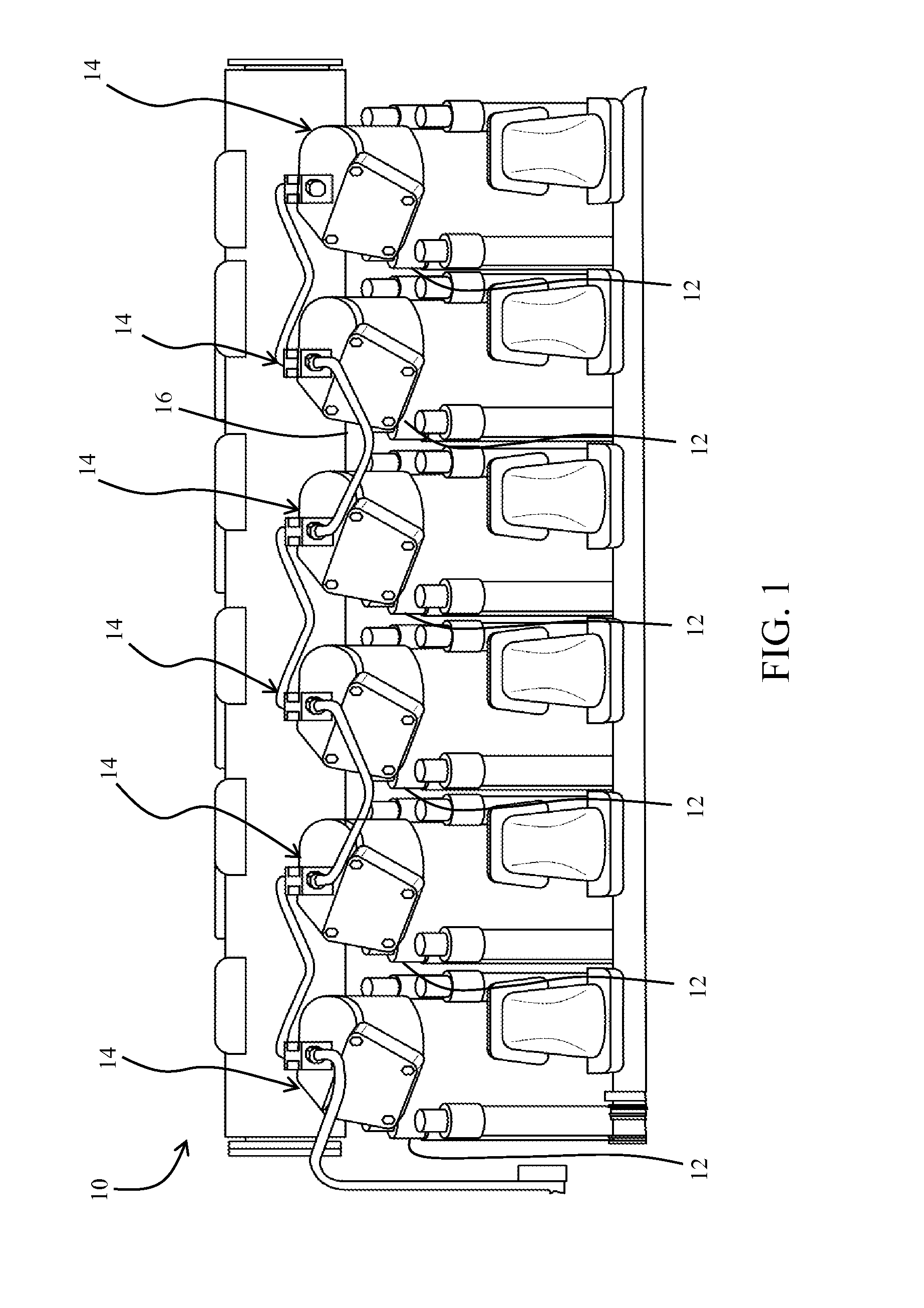
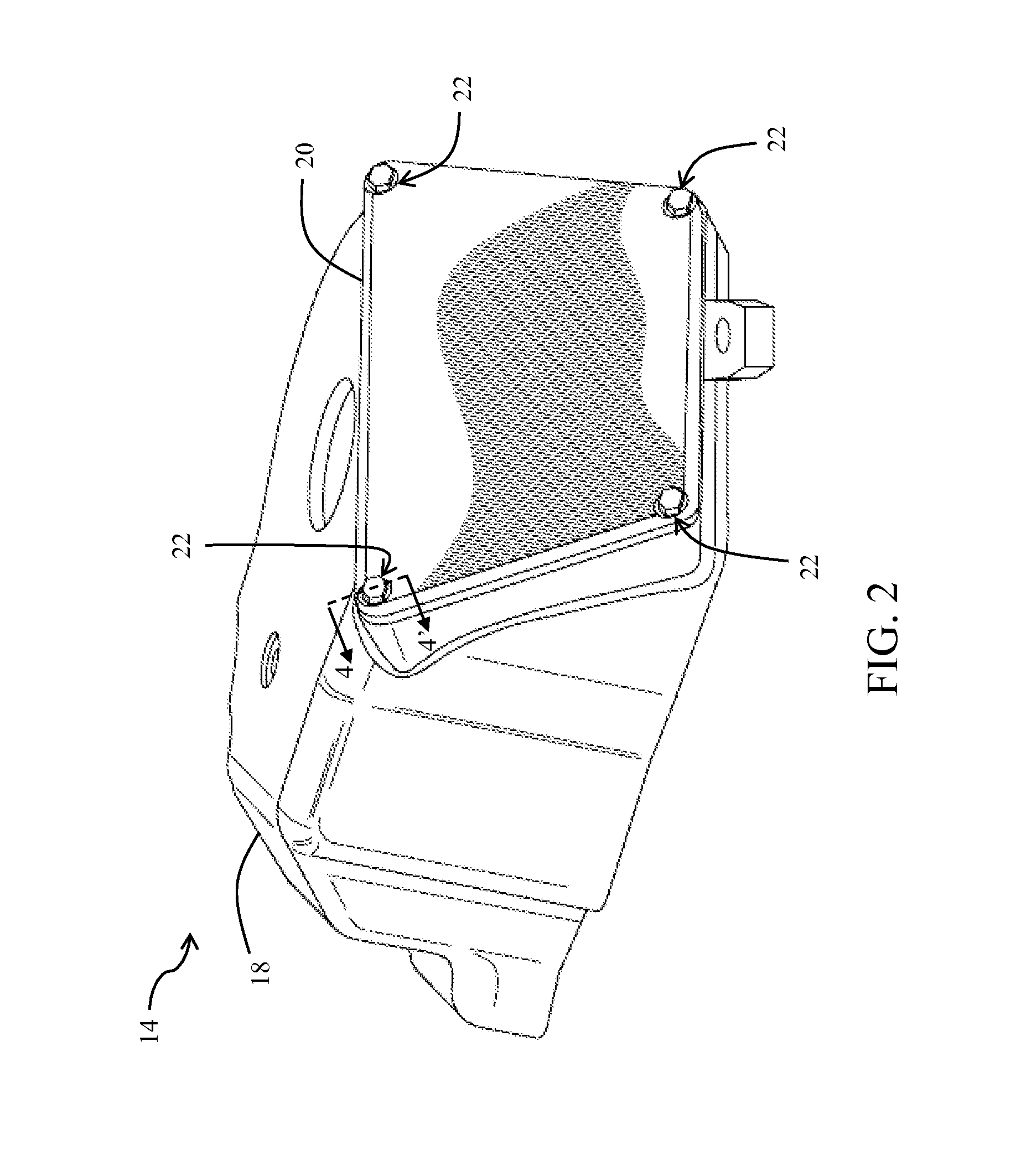
[0012]Referring to FIG. 1, there is shown an engine 10. Although not limited to, the engine 10 may be one of a spark ignition type and / or a compression ignition type. Other engine types may also be contemplated. Exemplarily, the engine 10 includes six in-line cylinders 12, each of which includes various mechanical components (not shown) arranged to perform one or more functions associated with the engine 10. The mechanical components (not shown) may include, but are not limited to, an intake valve, an exhaust valve, a rocker arm, and a rocker shaft. Additionally, the engine 10 employs six rocker cover assemblies 14, which co-relate to each of the six cylinders 12, and each of which is adapted to cover and protect the mechanical components (not shown) of each of the six cylinders 12 of the engine 10. More specifically, a rocker cover assembly 14 is mounted onto an engine block 16, such that the rocker cover assembly 14 covers the mechanical components (not shown) of a cylinder 12 of ...


PUM


Abstract

A rocker cover assembly for an engine is disclosed. The rocker cover assembly includes a base member, a cover plate, and at least one fastener unit that attach the cover plate to the base member. The base member includes fastener-receiving portions, each of which has a step between a first section and a second section. The second section includes an insert-receiving portion. The cover plate includes fastener holes axially aligned with the fastener-receiving portions of the base member. Each fastener unit includes a retaining insert, a push nut, and a threaded fastener. The retaining insert is fixedly attached to the insert-receiving portion. The push nut is co-axially positioned with the bore within the first section and against the step, to limit a travel of the push nut towards the second section. The threaded fastener includes a head section, a threaded section, and an extended shank section.

Description

TECHNICAL FIELD[0001]The present disclosure relates generally to fastener units for a rocker cover assembly of an engine. More specifically, the present disclosure relates to a fastener unit that facilitates removable attachment between a cover plate and a cover body of the rocker cover assembly, such that the fastener unit is retained with the cover plate upon a disassembly of the cover plate from the rocker cover assembly.BACKGROUND[0002]Engines, such as internal combustion engines, are commonly known to employ a rocker cover assembly that houses various engine components, such as a rocker arm, a rocker shaft, intake valves, and exhaust valves. Rocker cover assemblies generally include a cover body, a cover plate, and a number of threaded fasteners that facilitate a removable attachment of the cover plate to the cover body of the rocker cover assembly.[0003]In conventional rocker cover assemblies, the threaded fasteners extend through the cover plate and engage with a threaded bor...

Claims


Application Information

Patent Timeline
IPC IPC(8): F01L1/18F02B77/02
CPCF01L1/18F02B77/02F02B77/11B60L50/60Y02T10/70B60B35/1036B60B35/12B60B2320/10B60B2900/3312B60B2900/351F16C3/03F16H25/20
Inventor NIVARTHI, AMAR, J.
Owner ELECTRO-MOTIVE DIESEL
Learn More