LOW NOx COMBUSTION METHOD AND APPARATUS

a combustion method and low nox technology, applied in the field of heating systems, can solve the problems of reducing nox emission levels, reducing burning rates, and reducing flame temperatures, and achieve the effect of reducing nox emission and reducing nox emission

Active Publication Date: 2016-01-21
CHEVROU USA INC
View PDF7 Cites 12 Cited by
  • Summary
  • Abstract
  • Description
  • Claims
  • Application Information

AI Technical Summary

Benefits of technology

[0008]In one aspect, the invention relates to a burner system having low NOx emission of less than 5 ppm dry gas volumetric basis corrected to 3% O2 (i.e., <5 ppm at 3% O2, dry basis). The burner system comprises: a structure defining a combustion chamber; sources of primary fuel, combustion air, and secondary fuel; a premix burner having a port facing into the combustion chamber; a flue that draws products of combustion from the combustion chamber; a plurality of staged fuel injectors each having a port facing into the combustion chamber, wherein the staged fuel injectors are circumferentially arranged adjacent to and around the premix burner port; a premix injection apparatus configured to inject an unignited premix of secondary fuel and flue gas into the combustion chamber through the plurality of staged fuel injectors; a reactant supply and control system including means for conveying primary fuel from the primary fuel source to the premix burner, means for conveying combustion air from the combustion air source to the premix burner for mixing with the primary fuel, means for conveying secondary fuel from the secondary fuel source to the premix injection apparatus, and means for conveying flue gas from the flue to the injection apparatus for mixing with the secondary fuel.
[0009]In a second aspect, the invention relates to a method for operating a burner system to reduce its NOx emission. The method comprises: feeding a fuel stream and an air stream to a pre-mixer, wherein the fuel and air streams are mixed to form a first mixture at a fuel to air equivalence ratio of less than 1; injecting the first fuel air mixture via at least a primary port into a primary combustion zone of a combustion chamber, wherein the first fuel air mixture is substantially combusted forming primary products of combustion (“POC”); introducing the primary POC into a secondary combustion zone of the combustion chamber; feeding a second fuel stream and a stream of recirculated flue gas (RFG) to a pre-mixer, wherein the second fuel and recirculated flue gas streams are mixed to form a second fuel mixture; injecting the second fuel mixture into the secondary combustion zone of the combustion chamber via a plurality of injectors circumferentially arranged about the primary port; wherein the second fuel mixture is substantially combusted forming secondary POC; recirculating a portion of the combined primary POC and secondary POC for use as the RFG for mixing with the second fuel stream in pre-mixer; wherein the injection of the second fuel mixture into the secondary combustion zone of the combustion chamber results in a reduction of temperature in the combustion chamber for the NOx emission to be less than 5 ppm.
[0010]In a third aspect, the invention relates to a method of retrofitting a steam generator employing at least a fired burner with a flue gas recirculation system, wherein a recirculated flue gas (RFG) is injected with a fuel stream into a primary stage of the burner, the retrofit is to reduce NOx emission to less than 5 ppm. The method comprises: configuring the existing flue gas recirculation system to include a pre-mixer; routing the RFG from the primary stage to the pre-mixer for mixing with a portion of the fuel stream forming a secondary RFG fuel mixture; routing the secondary RFG fuel mixture to an existing secondary stage of the burner via a plurality of injectors for the injection of the second RFG fuel mixture results in a reduction of temperature for the NOx emission to be less than 5 ppm.

Problems solved by technology

In ULNBs, flue gas is internally recirculated using the pressure energy of fuel gas, which dilutes the fuel / air mixture and results in lower burning rates and reduced flame temperatures and subsequently, lower NOx emission levels.

Method used


Image

  • LOW NOx COMBUSTION METHOD AND APPARATUS
  • LOW NOx COMBUSTION METHOD AND APPARATUS
  • LOW NOx COMBUSTION METHOD AND APPARATUS

Examples


example

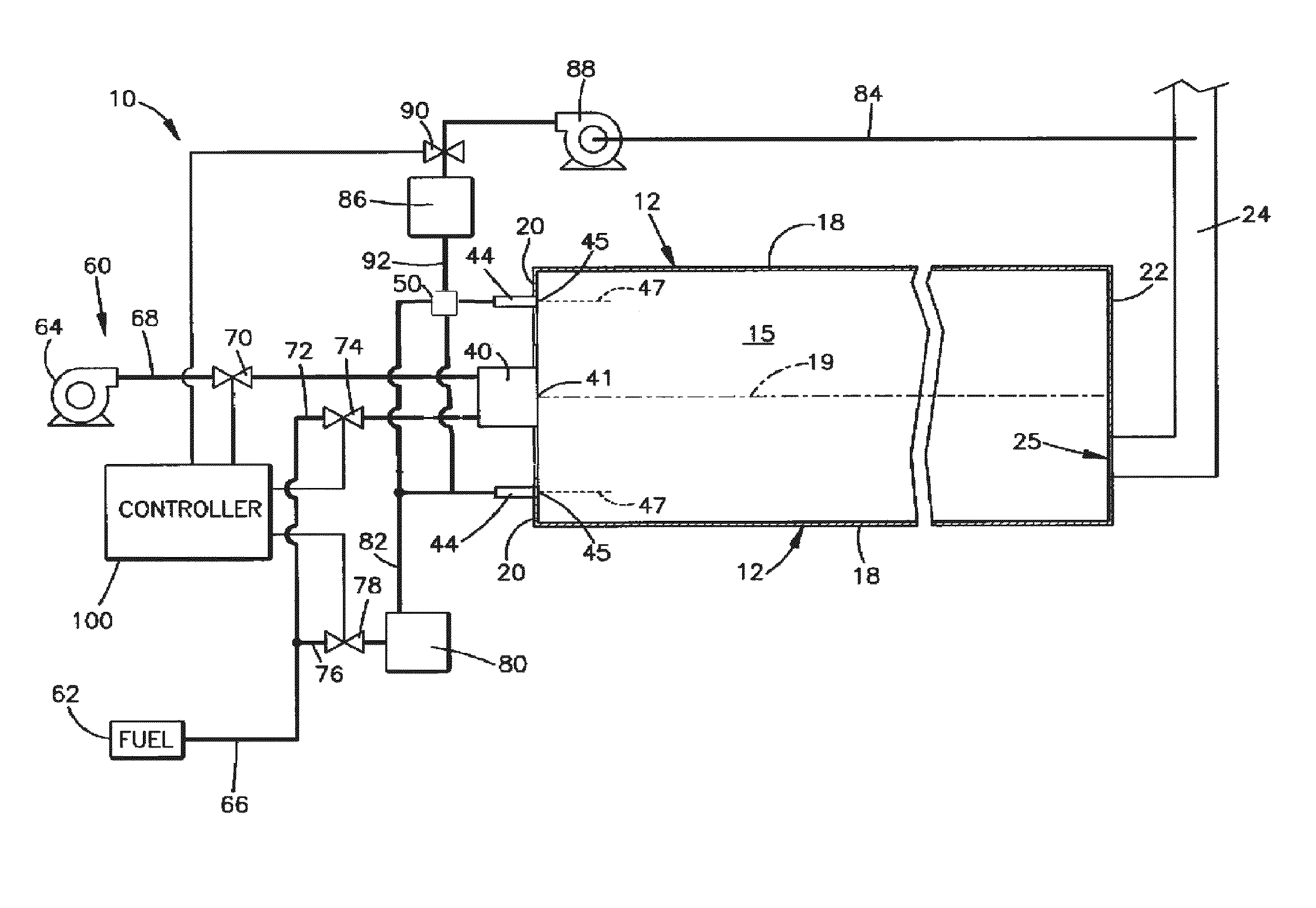
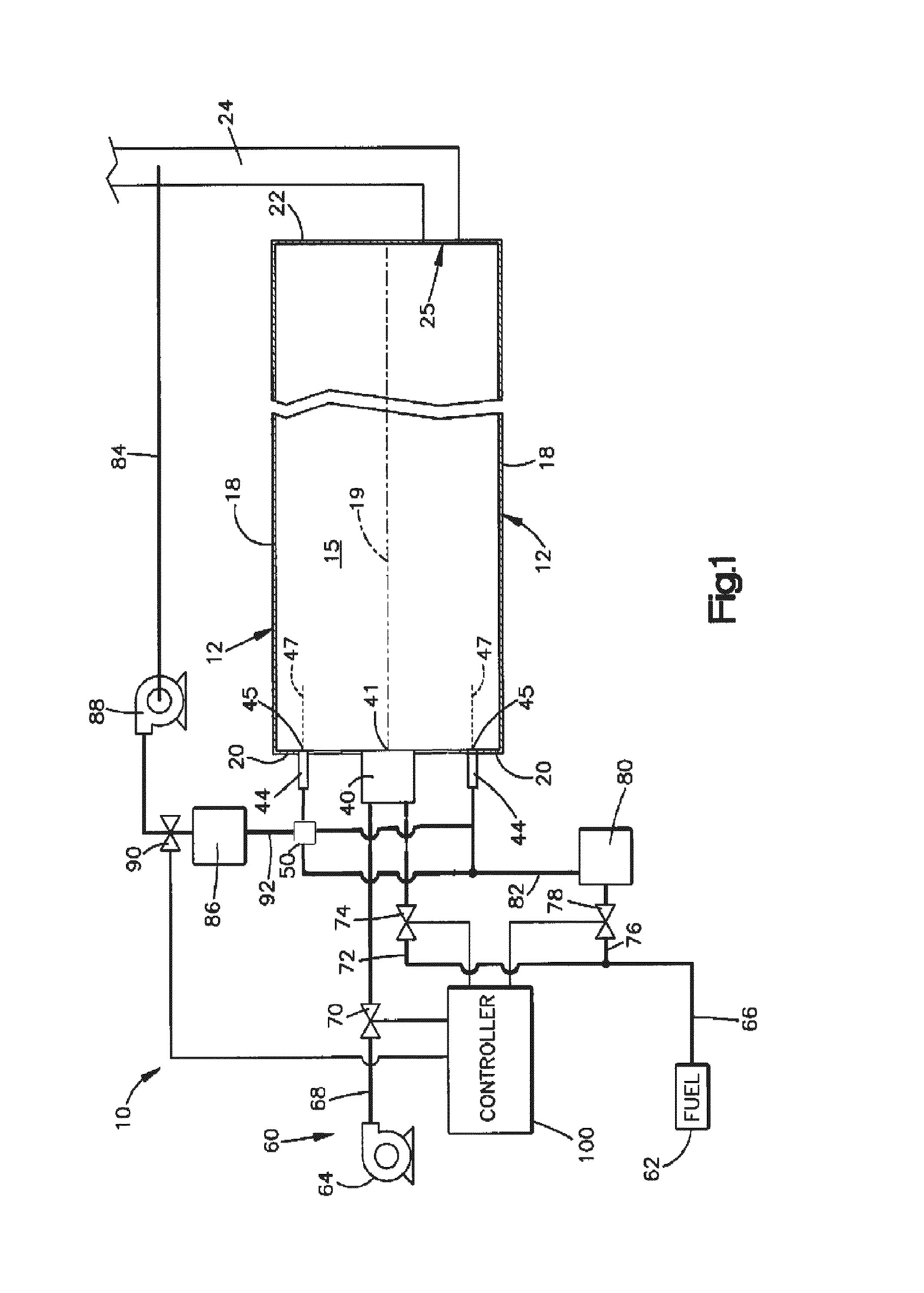
[0037]The following illustrative example is intended to be non-limiting. In this example, existing secondary gas inlets to a gas-fired combustion unit to provide low-quality, high pressure wet steam for an enhanced oil recovery operation were replaced with a premixed inlet of recycled flue gas and natural gas, with the total fuel input remains the same. The flue gas was removed directly from the stack and perfectly mixed with the fuel stream before it was introduced into the secondary combustion zone of the burner through a simple open pipe. The lean primary combustion zone remains unchanged.

[0038]Experimental data were collected from the steam generator, including ambient air flow rate, temperature, and fuel flow rate, temperature, and flue gas composition. Data collection was also made in the furnace radiant section at longitudinal locations with radial measurements taken from the furnace wall to the center of the steam generator. At each location, extractive sampling was utilized...


PUM


Abstract

A steam generator system employing a fired burner with a flue gas recirculation system with low NOx emission is disclosed. A method to retrofit fired burners for low NOx emission is also disclosed. In the system, the flue gas recirculation system is configured to include a pre-mixer, and the recirculated flue gas (RFG) is routed to the stage of the pre-mixer for mixing with a portion of the fuel stream, forming a secondary RFG fuel mixture. The secondary RFG fuel mixture is routed to the secondary stage of the burner via a plurality of injector ports. The injection of the second RFG fuel mixture results in a reduction of temperature for the NOx emission to be less than 5 ppm at 3% O2, dry basis.

Description

CROSS REFERENCE TO RELATED APPLICATIONS[0001]This application claims benefit under 35 USC 119 of U.S. Provisional Patent Application No. 62 / 024,689 with a filing date of Jul. 15, 2014. This application claims priority to and benefits from the foregoing, the disclosure of which is incorporated herein by reference.TECHNICAL FIELD[0002]This technology relates to a heating system in which combustion produces oxides of nitrogen (NOx), and specifically relates to a method and apparatus for suppressing the production of NOx.BACKGROUND[0003]Certain industrial processes, such as heating a load in a furnace or generating steam in a boiler, rely on heat produced by the combustion of fuel and oxidant in a combustion chamber. The fuel is typically natural gas. The oxidant is typically air, vitiated air or air enriched with oxygen. Combustion of the fuel and oxidant in the combustion chamber causes NOx to result from the combination of oxygen and nitrogen. It may be desirable to suppress the resu...

Claims


Application Information

Patent Timeline
Patent Type & Authority Applications(United States)
IPC IPC(8): F23C9/08F23C5/08F23D23/00F23K5/10
CPCF23C9/08F23C5/08F23K5/10F23D23/00F23C6/047F23C2202/20
Inventor ROBERTSON, THOMAS F.NOWAKOWSKI, JOHN J.HANNUM, MARK C.STORSLETT, STEIN J.
Owner CHEVROU USA INC
Why Eureka
Try Eureka