System and method for managing lubricant within a vapor compression heat pump

Active Publication Date: 2016-01-21
FORD GLOBAL TECH LLC
View PDF4 Cites 7 Cited by
  • Summary
  • Abstract
  • Description
  • Claims
  • Application Information

AI Technical Summary

Benefits of technology

[0002]A vehicle may include a heat pump for heating and cooling a passenger compartment. The heat pump may include a compressor for pressurizing refrigerant. The refrigerant may travel throughout the heat pump system and transfer heat between two or more different locations. The lubricant used in the compressor may be mixed with the refrigerant and the lubricant may travel throughout the heat pump system. Over time, lubricant may attach itself to the inner walls of the heat pump components, such as heat exchangers and refrigerant lines. This may reduce the amount of lubricant available to the compressor, resulting in compressor degra

Problems solved by technology

This may reduce the amount of lubricant available to the compressor, resulting in compressor degradation.
Further, lubricant may reduce the heat transfer characteristics of the heat exchangers.
An o

Method used


Image

  • System and method for managing lubricant within a vapor compression heat pump
  • System and method for managing lubricant within a vapor compression heat pump
  • System and method for managing lubricant within a vapor compression heat pump

Examples


Embodiment Construction

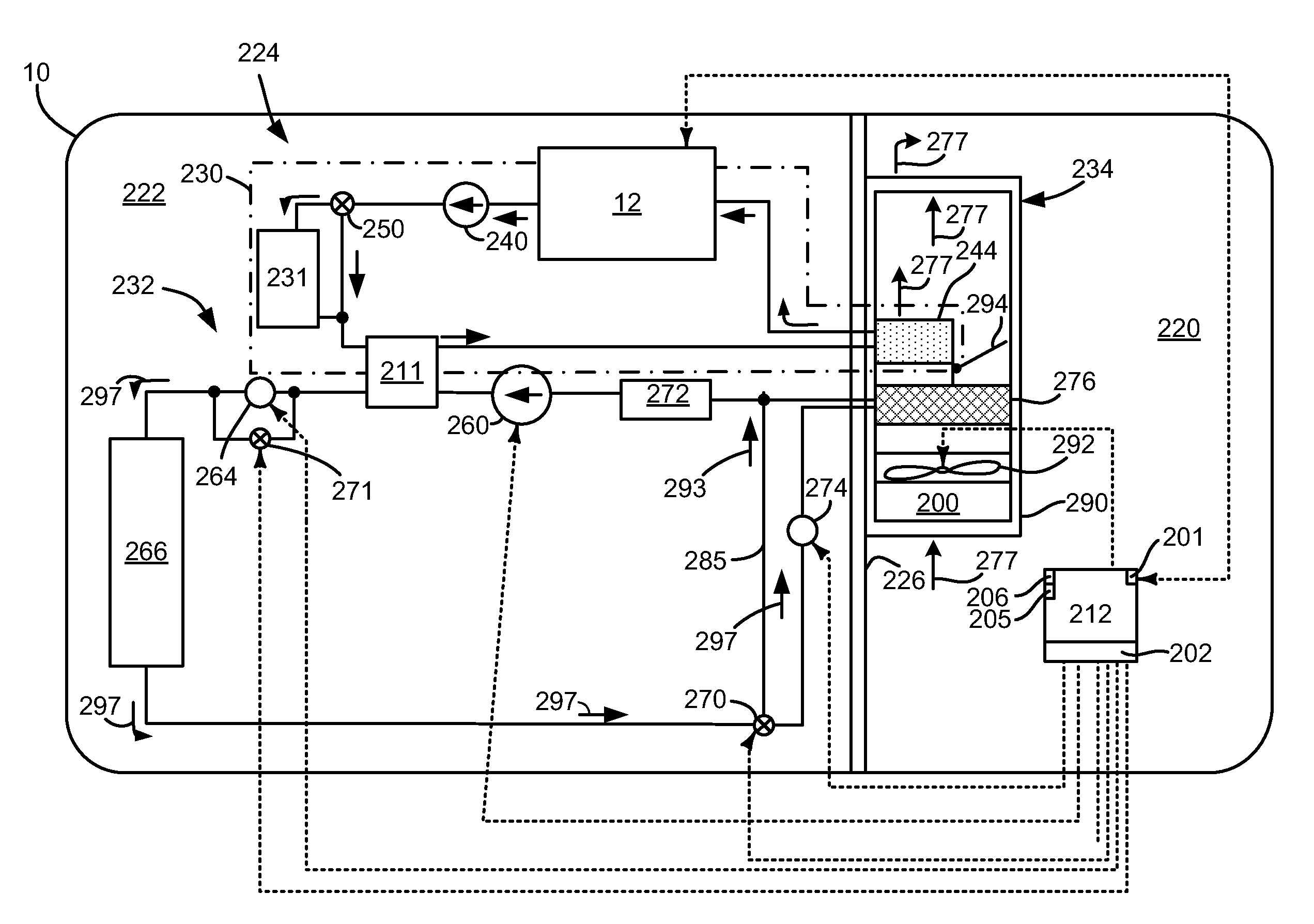
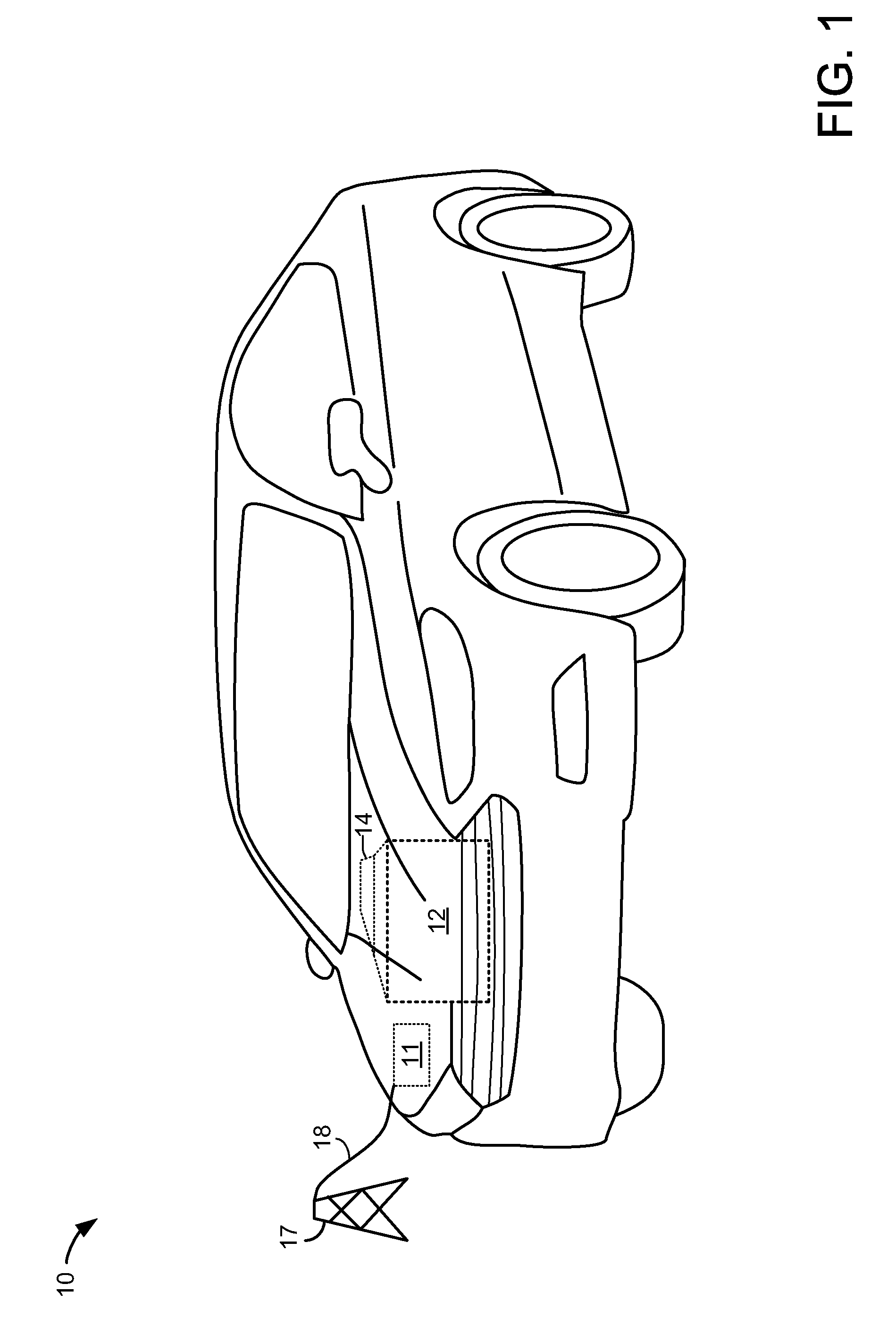
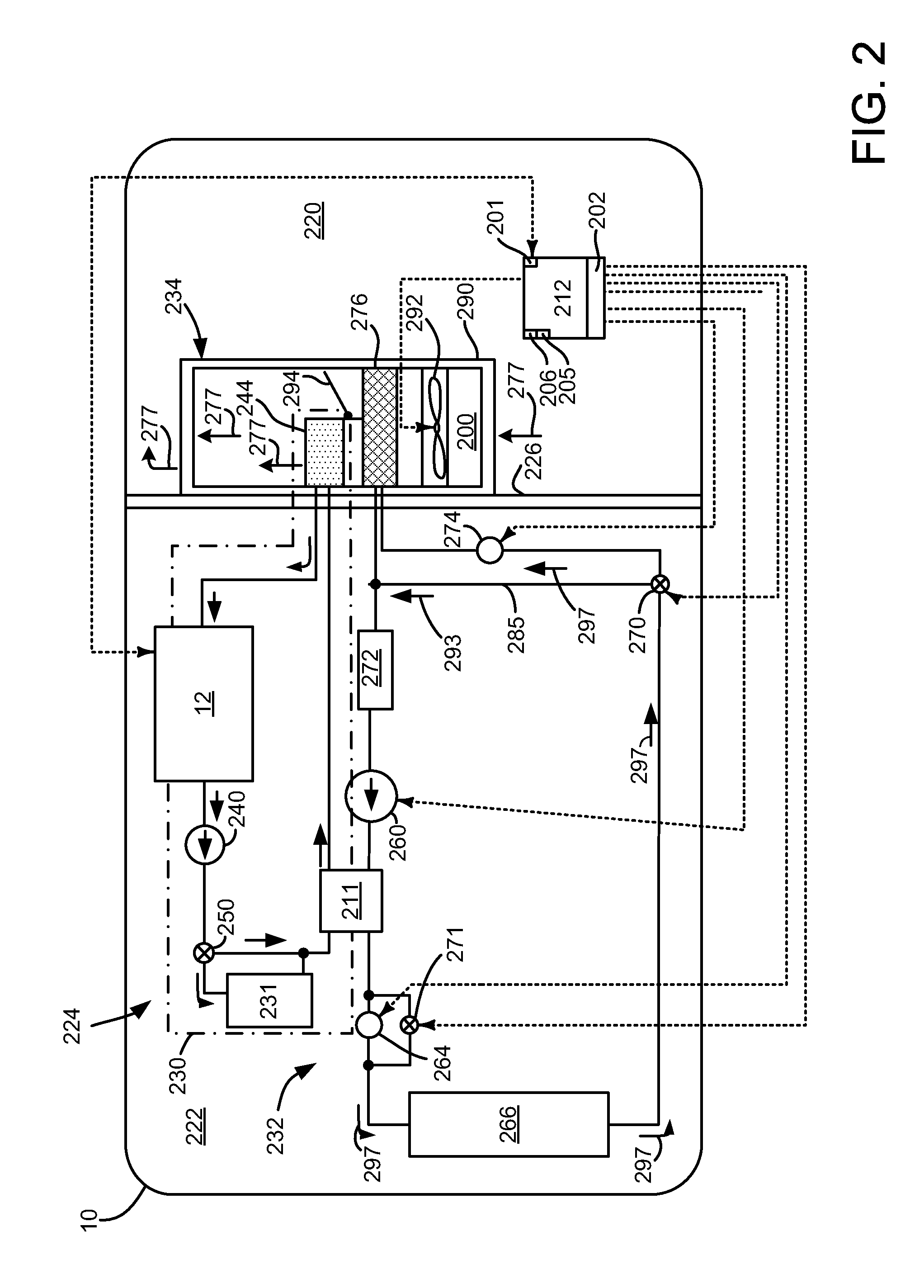
[0014]The present description is related to flushing of lubricant from refrigerant subsystem components where it is not desired. Specifically, lubricant may be flushed from such components by activating the compressor while the vehicle is operating and / or while the vehicle is not being operated. Components where lubricant has accumulated may be pressurized to force the lubricant to detach itself from inner walls of components and entrain with refrigerant, so that it may return to the compressor where it is used to lubricate the compressor. The vehicle may be a passenger vehicle as is shown in FIG. 1 or a commercial vehicle (not shown). The vehicle includes a climate control system including a heat pump as is shown in FIG. 2. The climate control system may include an engine that is part of a hybrid powertrain as is shown in FIG. 3. Lubricants may be flushed from the heat pump system components according to the method of FIG. 4. The lubricants may be flushed from the vehicle's heat pu...


PUM


Abstract

Methods and system for managing lubricant within a vapor compression heat pump are presented. In one example, lubricant may be flushed from selected areas of a heat pump to other areas of the heat pump where lubricant is desired. The lubricant may be flushed in full flushing mode or in a partial flushing mode.

Description

FIELD[0001]The present description relates to methods and a system for managing lubricant within a vapor compression heat pump of a vehicle. The methods and system may be particularly useful for vehicles that are propelled by an electrical device.BACKGROUND AND SUMMARY[0002]A vehicle may include a heat pump for heating and cooling a passenger compartment. The heat pump may include a compressor for pressurizing refrigerant. The refrigerant may travel throughout the heat pump system and transfer heat between two or more different locations. The lubricant used in the compressor may be mixed with the refrigerant and the lubricant may travel throughout the heat pump system. Over time, lubricant may attach itself to the inner walls of the heat pump components, such as heat exchangers and refrigerant lines. This may reduce the amount of lubricant available to the compressor, resulting in compressor degradation. Further, lubricant may reduce the heat transfer characteristics of the heat exc...

Claims


Application Information

Patent Timeline
IPC IPC(8): F25B47/00
CPCF25B47/00B60H1/00385B60H1/00921B60H1/3214B60H2001/00928F25B5/04F25B6/04F25B25/005F25B41/39
Inventor RAGAZZI, FRANCO
Owner FORD GLOBAL TECH LLC
Why Eureka
Try Eureka