Heat pipe

a heat pipe and heat conductivity technology, applied in the field of heat pipes, can solve the problems of insufficient flow of vapor through the vapor passages, insufficient return of working fluid to the evaporating portion, and weakened capillary pumping of the wick, so as to achieve enhanced heat transport capacity reduce the thermal resistance of the heat pipe, and increase the heat conductivity of carbon

Active Publication Date: 2016-01-21
THE FUJIKURA CABLE WORKS LTD
View PDF10 Cites 12 Cited by
  • Summary
  • Abstract
  • Description
  • Claims
  • Application Information

AI Technical Summary

Benefits of technology

[0012]The present invention has been conceived nothing the foregoing technical problems, and it is therefore an object of the present invention is to provide a flat heat pipe having enhanced heat transport capacity that can be manufactured easily.
[0017]A melting point of copper is lower than that of carbon. According to the present invention, the second wick made of carbon fibers are neither bonded to one another nor fixed to the inner face of the container at the sintering temperature of the first wick formed of the copper fibers, but it can be held by the sintered first wick on the inner face of the container. In addition, heat conductivity of carbon is higher than that of copper. According to the present invention, therefore, thermal resistance of the heat pipe can be reduced by thus forming the second wick made of carbon fibers so that heat transport capacity of the heat pipe can be enhanced. Further, the heat pipe thus having two kinds of wicks can be manufactured easily without applying binder agent or the like to the carbon wick.

Problems solved by technology

In the heat pipe of this kind, the vapor is not allowed to flow through the vapor passages in sufficient amount.
Nonetheless, if number of fibers forming the wick is reduced to expand the vapor passage in the heat pipe taught by JP-A-2013-002641, the capillary pumping of the wick may be weakened and hence the working fluid cannot be returned sufficiently to the evaporating portion.
In addition, it is difficult to arrange a wick structure having a complicated structure in the thin flat sealed container and there is a need for simplifying manufacturing of the heat pipes.

Method used


Image

  • Heat pipe
  • Heat pipe
  • Heat pipe

Examples


Embodiment Construction

)

[0027]Hereinafter, preferred examples of the heat pipe according to the present invention will be explained in more detail with reference to the accompanying drawings.

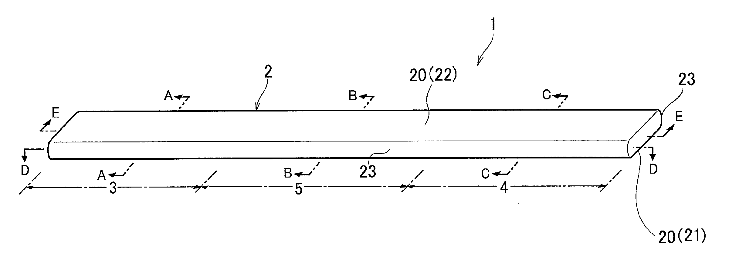
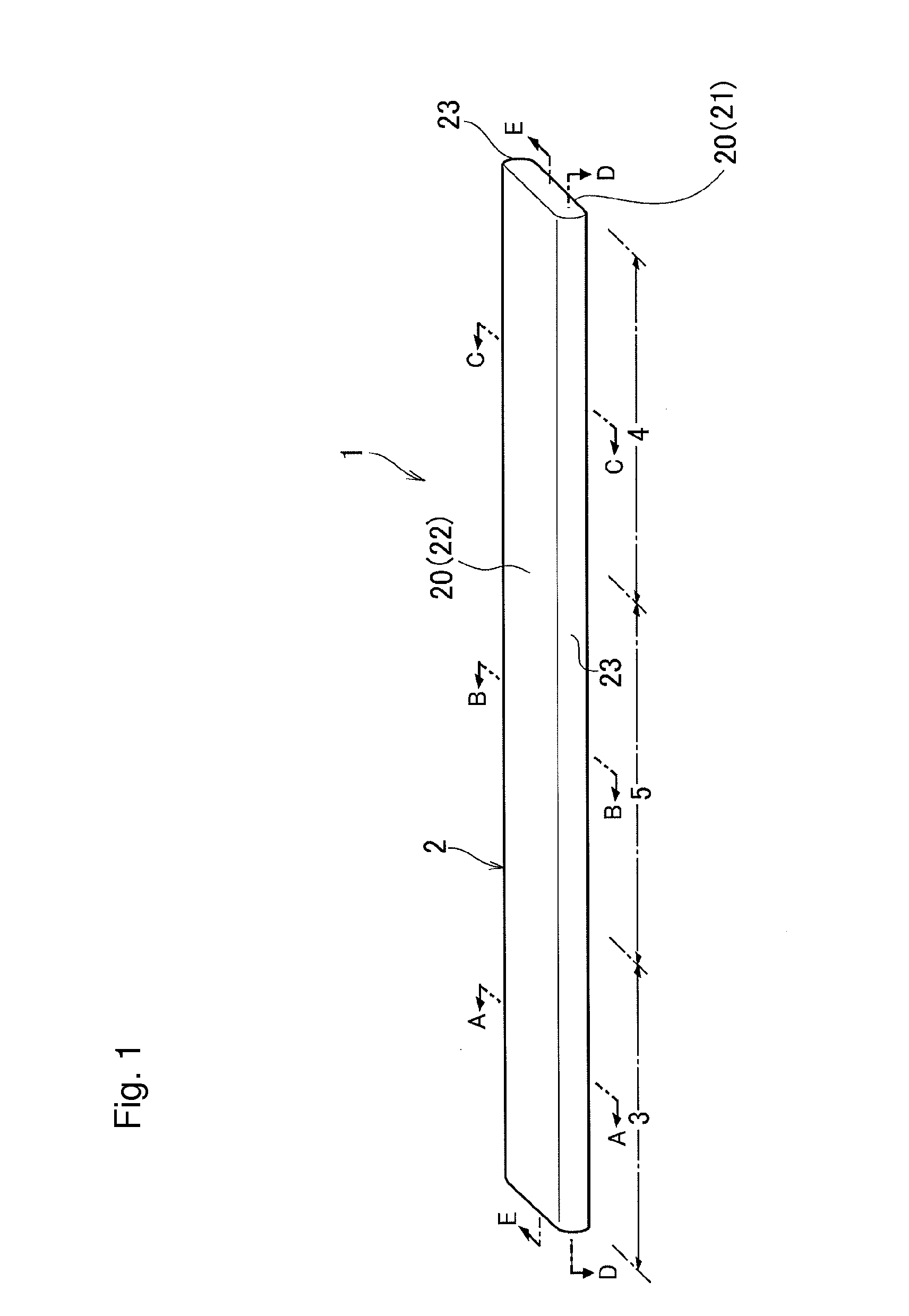
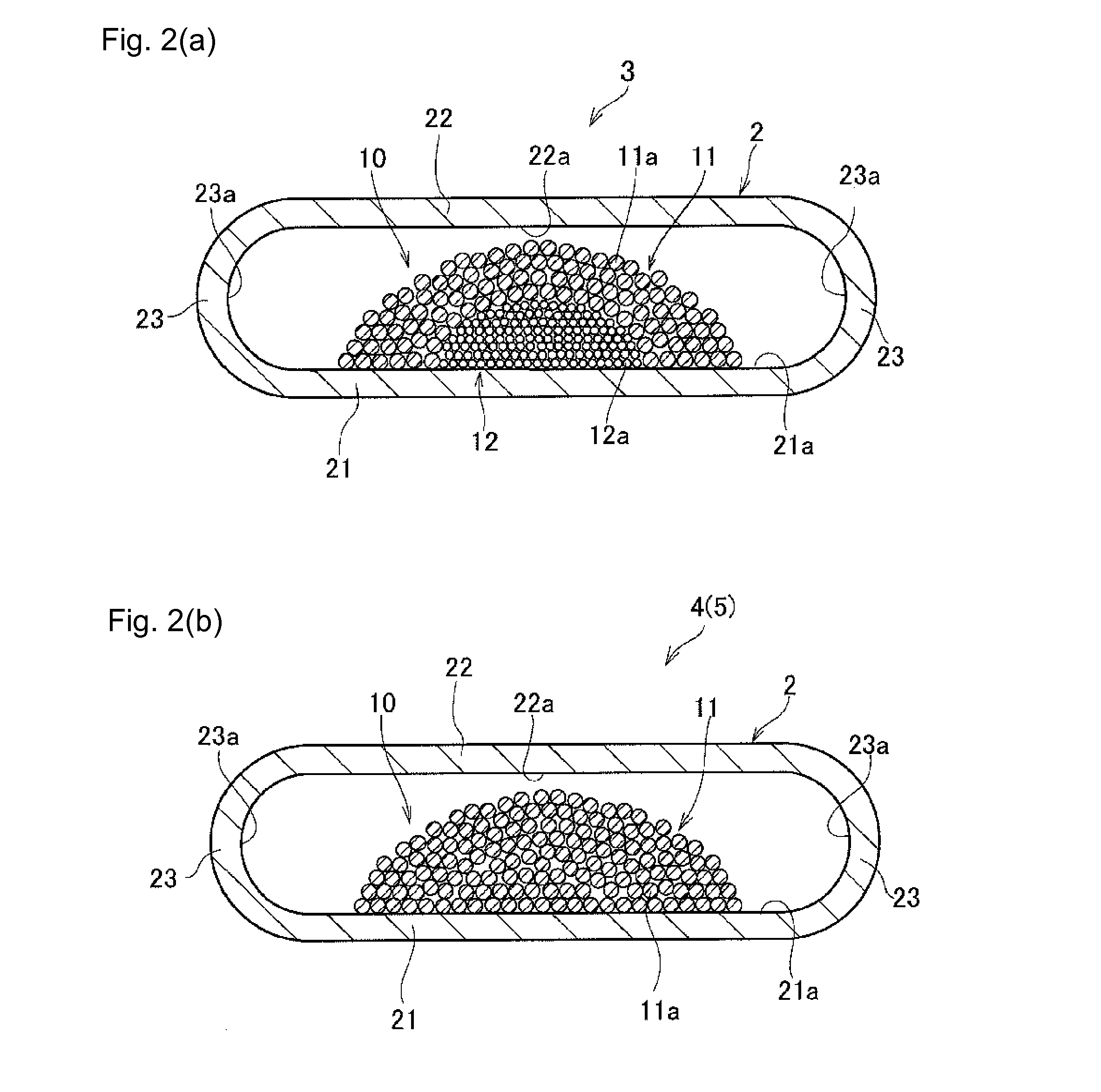
[0028]Referring now to FIG. 1, there is shown a heat pipe 1 according to the first example. The heat pipe 1 shown therein is a heat transport device adapted to transport heat in the form of latent heat of working fluid encapsulated in a sealed container 2. The container 2 is a hollow container made of metal plate having a constant thickness and high heat conductivity such as a copper plate, a steel plate, an aluminum plate and so on, and flattened to have wider width and sealed at both longitudinal ends.

[0029]The container 2 is comprised of a flat wall 20 having a predetermined width and a curved side wall 23. The flat wall includes a lower flat wall 21 and an upper flat wall 22.

[0030]For example, a known phase changeable liquid such as water, alcohol, ammonia etc. may be used as a working fluid (not shown) for transp...


PUM


Abstract

A heat pipe having enhanced heat transport capacity that can be manufactured easily is provided. The heat pipe 1 comprises a sealed container 2 and a wick structure 10. The wick structure includes a first wick 11 formed of copper fibers 11a, and a second wick formed of carbon fibers 12a. The first wick 11 is sintered to be fixed to an inner face 21a of a flat wall 21 while holding the second wick 12 therein.

Description

[0001]The present invention claims the benefit of Japanese Patent Application No. 2014-145301 filed on Jul. 15, 2014 with the Japanese Patent Office, the disclosure of which is incorporated herein by reference in its entirety.BACKGROUND[0002]1. Field of the Invention[0003]The present invention relates to an art of a heat pipe having a wick structure.[0004]2. Discussion of the Related Art[0005]Heat pipes have been widely used as a heat transport device. The conventional heat pipe comprises a tubular sealed container and working fluid encapsulated therein, and brought into contact to a heat generating member. The working fluid is vaporized by a heat of the heat generating element transmitted to one end of the heat pipe and aspirated to the other end side due to difference in pressure inside and outside.[0006]The end portion of the heat pipe thus brought into contact to the heat generating element serves as an evaporating portion where evaporation of the working fluid takes place, and ...

Claims


Application Information

Patent Timeline
Patent Type & Authority Applications(United States)
IPC IPC(8): F28D15/04
CPCF28D15/04F28D15/0233F28D15/046
Inventor AHAMED, MOHAMMAD SHAHEDSAITO, YUJI
Owner THE FUJIKURA CABLE WORKS LTD
Why Eureka
Try Eureka