Stator of Rotating Electric Machine

a technology of rotating electric machines and rotating shafts, which is applied in the direction of windings, coupling device connections, cooling/ventilation arrangements, etc., can solve the problems of affecting the heat exchange efficiency of the rotating shaft, so as to improve heat exchange efficiency and heat exchange efficiency. , the effect of lowering the temperature of the phase windings

Active Publication Date: 2016-01-21
DENSO CORP
View PDF7 Cites 19 Cited by
  • Summary
  • Abstract
  • Description
  • Claims
  • Application Information

AI Technical Summary

Benefits of technology

[0020]In the third invention, the phase windings are configured such that respective planar outer peripheral surfaces oppose those of other phase windings having differing electrical phases on at least one end side in the axial direction of the stator core, and are each composed of a plurality of parallel windings, each of which are connected in parallel. The end portions of the phase windings are respectively electrically connected to heat releasing members that have conductivity. Therefore, when the stator winding generates heat as a result of being energized, the heat releasing members can draw the heat from the phase windings and release the heat outside, thereby lowering the temperature of the phase windings. As a result, the occurrence of insulation defects caused by thermal degradation and abnormal heat generation in the insulating films of the conductor segments configuring the phase windings can be prevented.
[0021]In addition, each of the phase windings include a plurality of parallel windings, each of which are connected in parallel. Therefore, surface areas of the phase windings can be increased and heat releasability can be improved, thereby enabling the occurrence of insulation defects to be prevented with further certainty.

Problems solved by technology

The bus bar disclosed in above-mentioned JP-A-2013-211945 may become damaged as a result of stress attributed to temperature difference caused by the difference in density of the current flowing through the bus bar.
Therefore, when the insulation capability of an insulating film that covers the outer circumferential surface of a conductor line decreases as a result of abnormal heat generation or thermal degradation, insulation defects may occur.

Method used


Image

  • Stator of Rotating Electric Machine
  • Stator of Rotating Electric Machine
  • Stator of Rotating Electric Machine

Examples


first embodiment

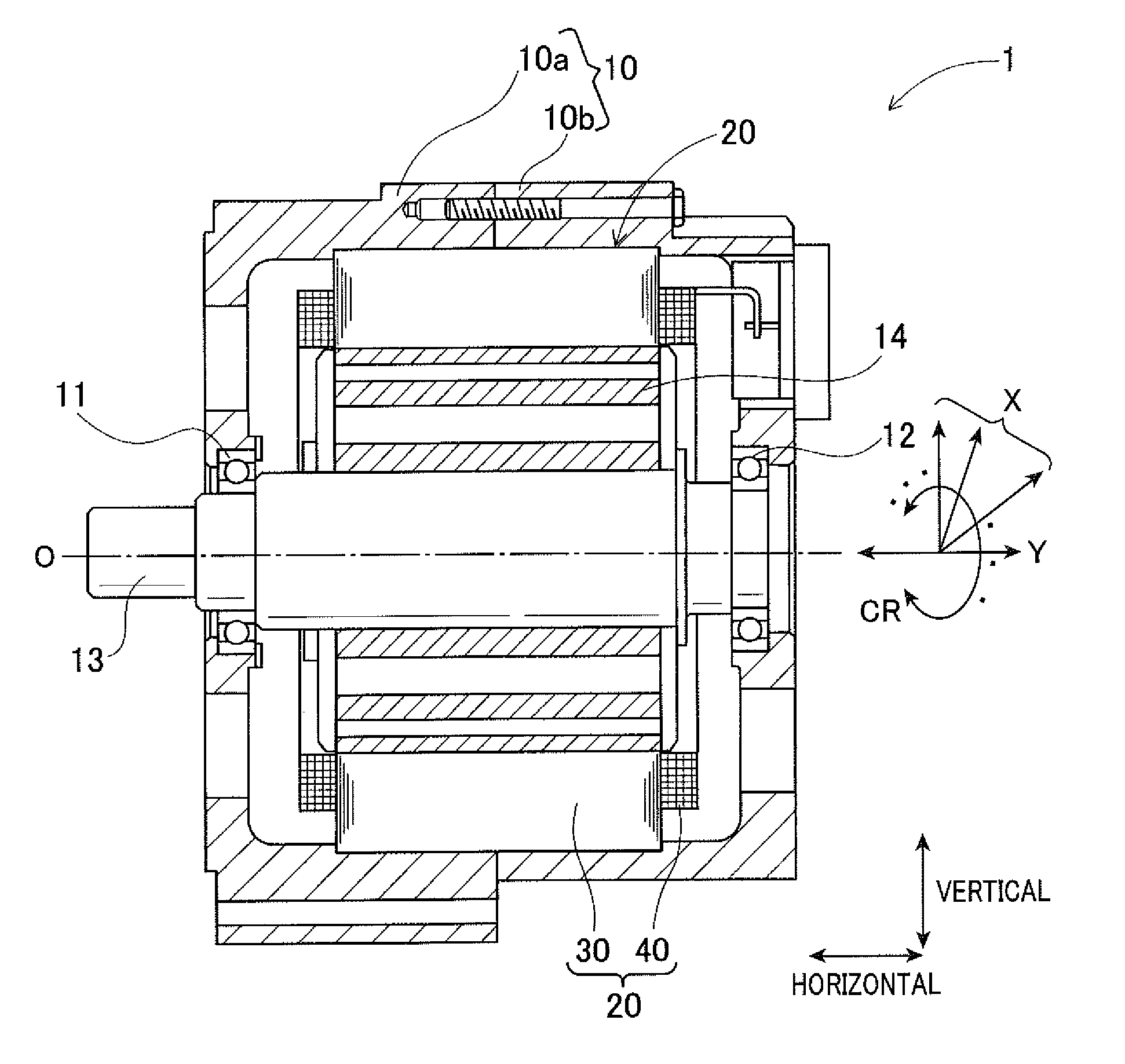
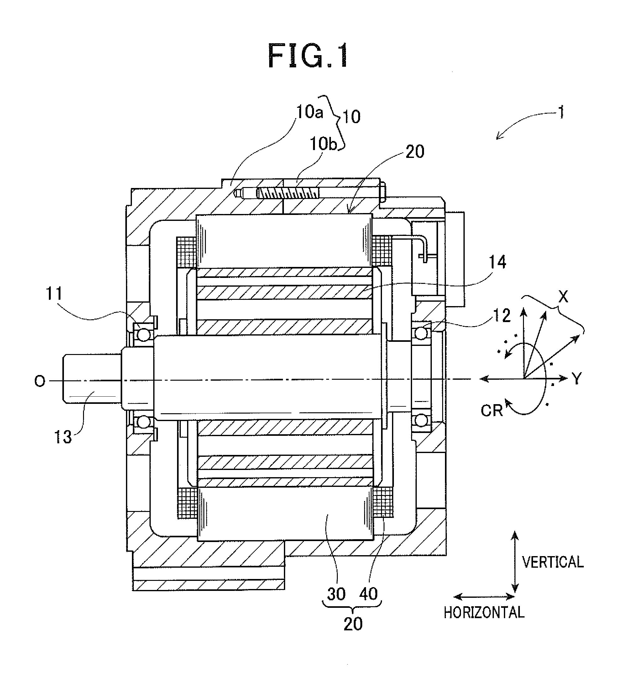
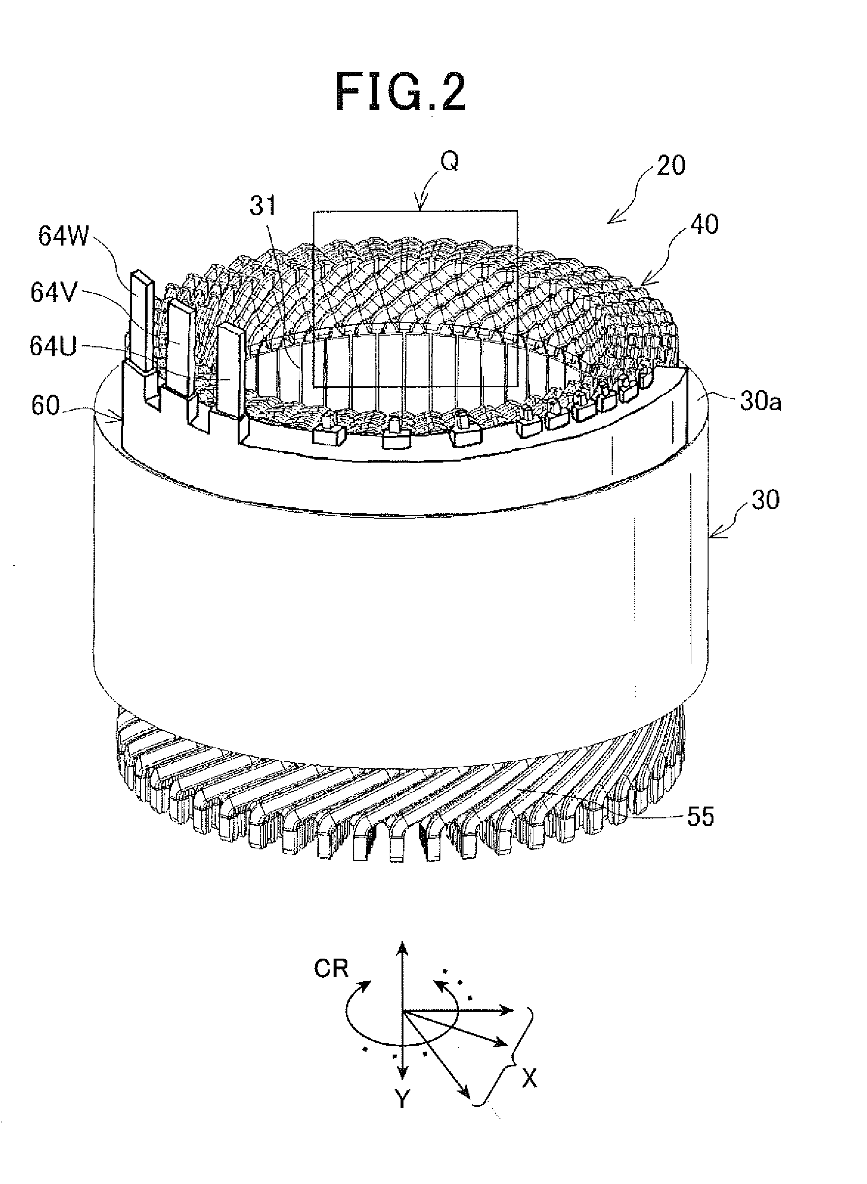
[0068]FIG. 1 shows a rotating electric machine 1 in which a stator 20 according to the present embodiment is mounted. This rotating electric machine 1 is used as an electric motor for a vehicle. As shown in FIG. 1, the rotating electric machine 1 includes a housing 10 that is composed by a pair of bottomed tube-shaped housing members 10a and 10b being joined together at respective opening portions, a rotating shaft 13 that is supported so as to rotate freely in the housing 10 by bearings 11 and 12, a rotor 14 that is fitted onto the outer circumference of the rotating shaft 13 and fixed thereto, and a stator 20 that is disposed so as to oppose the rotor 14 in a radial direction X of the rotating electric machine 1 on the outer side of the rotor 14.

[0069]The rotor 14 has a plurality of magnetic poles disposed on the outer circumferential side opposing the inner circumferential side of the stator 20 in the radial direction X, so as to be spaced apart by a predetermined distance in the...

second embodiment

[0090]A stator (not shown) of a rotating electric machine according to a second embodiment is the same as that according to first embodiment in terms of basic configuration. However, the stator according to the second embodiment differs from that according to the first embodiment in that the number of parallel windings configuring each phase winding 41U, 41V, and 41W of the stator winding 40 is four (four parallel windings when n=4), and regarding the structure of a bus bar module 70. Therefore, members and configurations that are shared with the first embodiment are given the same reference numbers, and detailed descriptions thereof are omitted. Differences and important features will hereinafter be described.

[0091]As shown in FIG. 10, in the stator winding 40 according to the second embodiment, the winding end of each phase winding 41U, 41V, and 41W is connected by a Y-connection. The phase windings 41U, 41V, and 41W are respectively composed of four parallel windings U1 to U4, V1...

third embodiment

[0103]FIG. 16 shows a rotating electric machine 101 in which a stator 120 according to a third present embodiment is mounted. This rotating electric machine 101 is used as an electric motor for a vehicle. As shown in FIG. 16, the rotating electric machine 101 includes a housing 110 that is composed by a pair of bottomed tube-shaped housing members 110a and 110b being joined together at respective opening portions, a rotating shaft 113 that is supported so as to rotate freely in the housing 110 by bearings 111 and 112, a rotor 114 that is fitted onto the outer circumference of the rotating shaft 113 and fixed thereto, and a stator 120 that is disposed so as to oppose the rotor 114 in a radial direction X of the rotating electric machine 101 on the outer side of the rotor 114.

[0104]The rotor 114 has a plurality of magnetic poles disposed on the outer circumferential side opposing the inner circumferential side of the stator 120 in the radial direction X, so as to be spaced apart by a ...


PUM


Abstract

In a stator of a rotating electric machine, an annular stator core has slots. A stator winding includes phase windings of three phases of differing electrical phases that are housed in the slots and wound around the stator core. Three phase bus bars electrically connect the respective phase windings to an external apparatus. Each of the phase windings are configured by multiple parallel windings. The phase bus bars are integrated with a fixing member to form a bus bar module. Each of the phase bus bars include branch portions and a trunk portion. The branch portions are electrically connected to the respective phase windings. The trunk portion electrically connects together the branch portions, and is configured that a cross-sectional area of an end portion closest to the phase winding is smaller than a cross-sectional area of an end portion closest to the external apparatus.

Description

CROSS-REFERENCE TO RELATED APPLICATION[0001]This application is based on and claims the benefit of priority from Japanese Patent Application Nos. 2014-148086, filed Jul. 18, 2014, 2014-148088, filed Jul. 18, 2014, and 2014-148105, filed Jul. 18, 2014. The entire disclosures of each of the above applications are incorporated herein by reference.BACKGROUND[0002]1. Technical Field[0003]The present disclosure relates to a stator of a rotating electric machine that is mounted in a vehicle or the like, and used as an electric motor or a power generator.[0004]2. Related Art[0005]As a rotating electric machine that is used so as to be mounted in a vehicle, a rotating electric machine that includes a rotor provided in a rotatable manner, and a stator having a stator core and a stator winding is commonly known. In this rotating electric machine, the stator core is disposed so as to oppose the rotor in a radial direction and has a plurality of slots that are arrayed in a circumferential direct...

Claims


Application Information

Patent Timeline
Patent Type & Authority Applications(United States)
IPC IPC(8): H02K3/28H01R25/16H02K3/12H02K9/00
CPCH02K3/28H02K3/12H01R25/16H02K9/00H02K9/19H02K2203/09H02K2213/03H02K3/50H02K9/227
Inventor TAMURA, AKITO
Owner DENSO CORP
Why Eureka
Try Eureka