Heat exchanger arrangement, especially for a vehicle heater

Active Publication Date: 2016-01-28
EBERSPACHER CLIMATE CONTROL SYST GMBH
View PDF5 Cites 5 Cited by
  • Summary
  • Abstract
  • Description
  • Claims
  • Application Information

AI Technical Summary

Benefits of technology

The present invention aims to provide a heat exchanger arrangement for a vehicle heater that reduces heat loss. The design is stable and simple with multiple recesses that follow each other in the circumferential direction. This design helps to ensure efficient heating of fluid and the removal of combustion waste gases. Openings for fluid inlet, outlet, and waste gas are provided in the second axial end area, and the depth of the recesses is optimized to increase thermal resistance. The heat-insulating effect of the recesses can be further improved by using insulating material with lower thermal conductivity.

Problems solved by technology

Since the two heat exchanger housings, but at least the inner heat exchanger housing, which is exposed more heavily to the hot combustion waste gases, is made, in general, of a metallic material, for example, die-cast aluminum, the preparation of recesses in this material, of which the heat exchanger housing is made, leads to an interruption in the metallic material.

Method used


Image

  • Heat exchanger arrangement, especially for a vehicle heater
  • Heat exchanger arrangement, especially for a vehicle heater
  • Heat exchanger arrangement, especially for a vehicle heater

Examples


Embodiment Construction

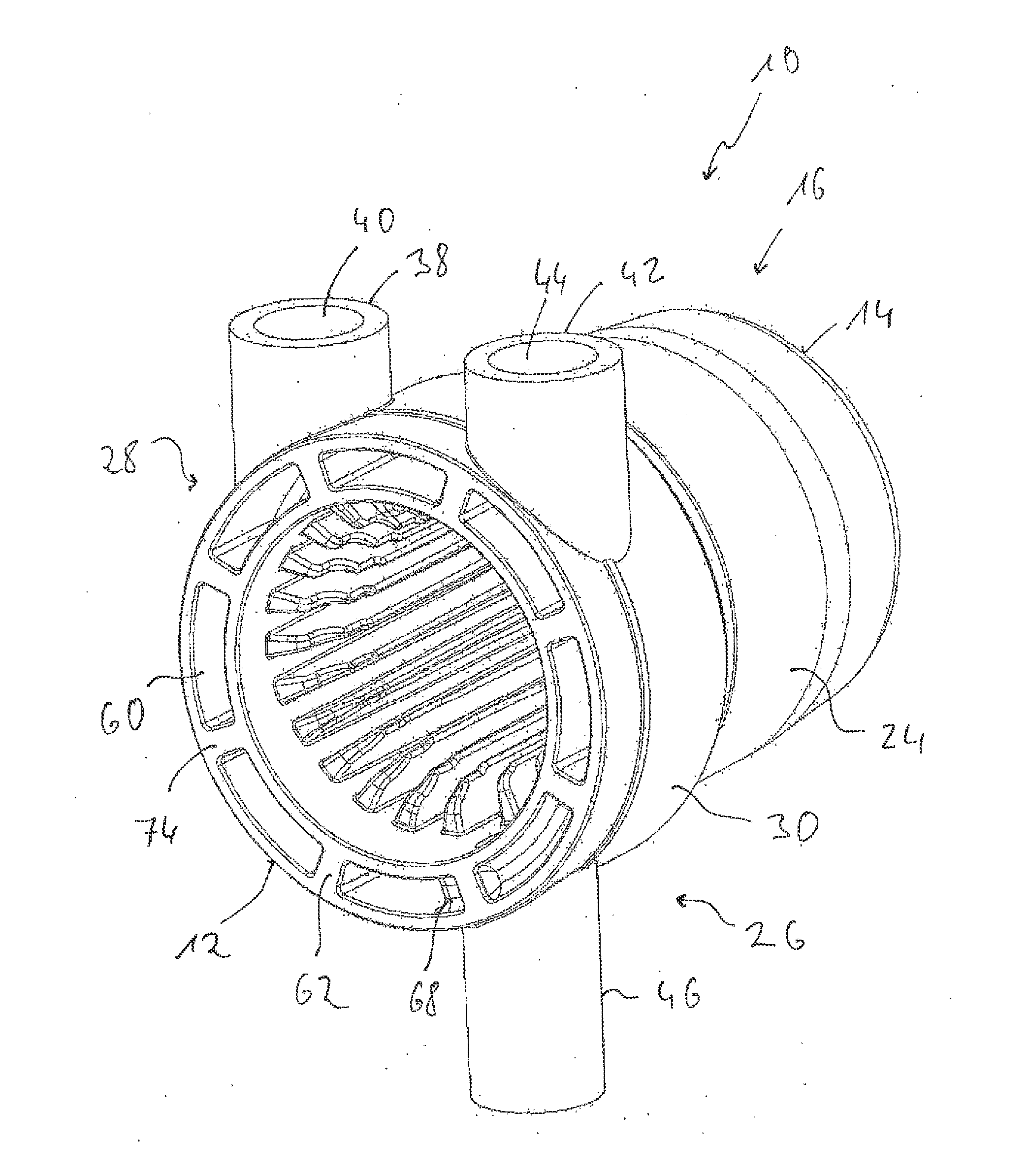
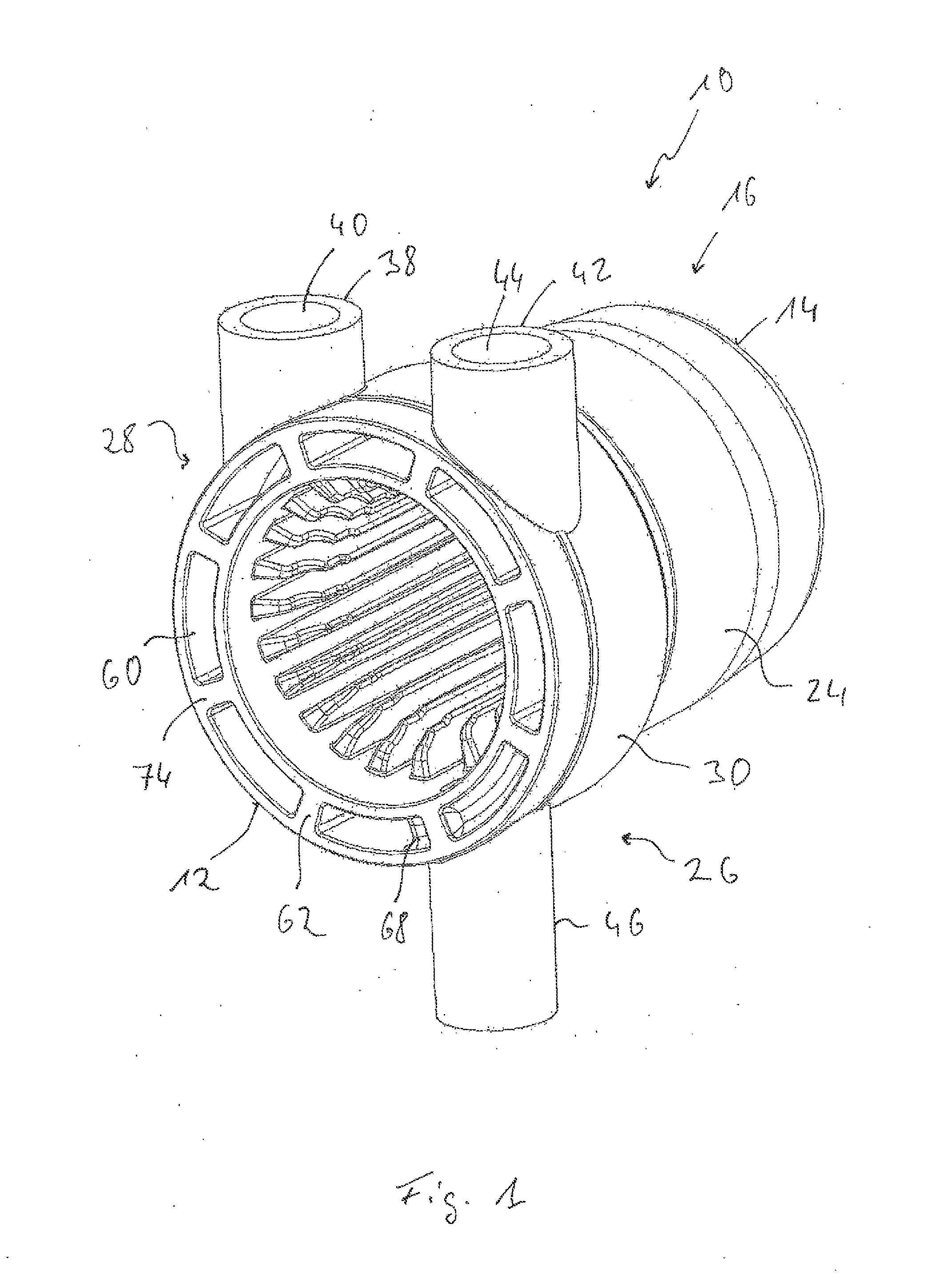
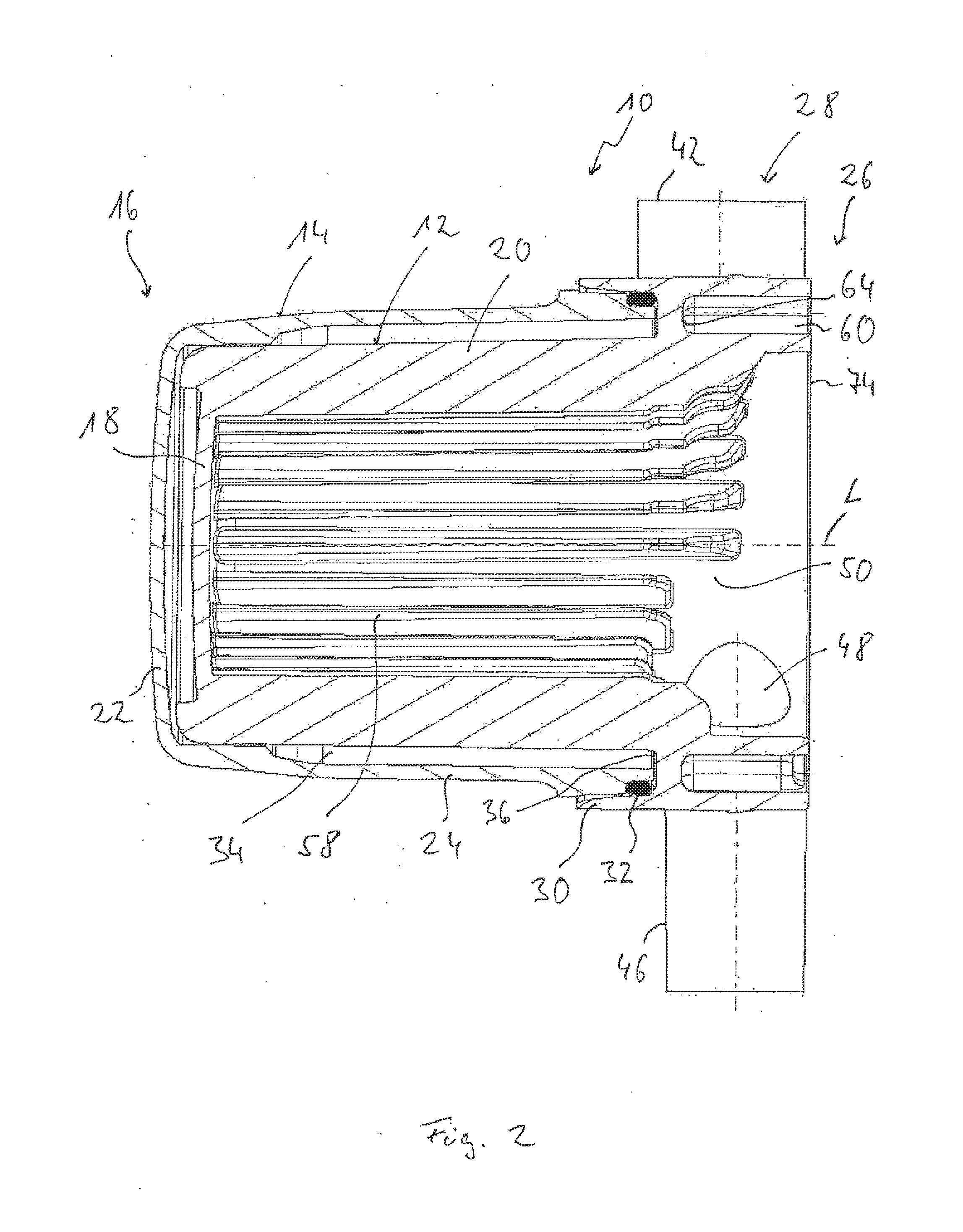
[0026]Referring to the drawings, a heat exchanger arrangement, which can be used, for example, in conjunction with a fuel-operated vehicle heater, is generally designated by 10 in the figures. The heat exchanger arrangement 10 comprises two heat exchanger housings 12, 14 inserted into one another. The inner heat exchanger housing 12 comprises in a first axial end area 16 of the heat exchanger arrangement 10 a first bottom wall 18 and, adjoining this radially on the outside and extending in the direction of a longitudinal axis L and enclosing the longitudinal axis L, a first circumferential wall 20. The outer heat exchanger housing 14 also comprises in a first axial end area 16 of the heat exchanger arrangement 10 a second bottom wall 22 as well as, adjoining same radially on the outside, a second circumferential wall 24 extending in the direction of the longitudinal axis L and enclosing same. It should be noted here that the two heat exchanger housings 12, 14 with their bottom walls...


PUM


Abstract

A vehicle heater heat exchanger arrangement (10) includes: a pot-like heat exchanger housing (12) with a first bottom wall (18) in a first axial end area (16) and with a first circumferential wall (20) adjoining the first bottom wall and enclosing a longitudinal axis (L); and a pot-like outer heat exchanger housing (14) with a second bottom wall (22) in the first axial end area and with a second circumferential wall (24) adjoining the second bottom wall and enclosing the longitudinal axis. The inner heat exchanger housing and the outer heat exchanger housing are connected to one another in a second axial end area (26) and a fluid flow space (34) is formed between the inner heat exchanger housing and the outer heat exchanger housing. The second axial end area has an outwardly open recess (60) defined by the inner heat exchanger housing or / and by the outer heat exchanger housing.

Description

CROSS REFERENCE TO RELATED APPLICATIONS[0001]This application claims the benefit of priority under 35 U.S.C. §119 of German Patent Application DE 10 2014 214 768.9 filed Jul. 28, 2014, the entire contents of which are incorporated herein by reference.FIELD OF THE INVENTION[0002]The present invention pertains to a heat exchanger arrangement, especially for a vehicle heater, comprising a pot-like (pot-shaped) inner heat exchanger housing with a first bottom wall in a first axial end area of the heat exchanger arrangement and with a first circumferential wall adjoining the first bottom wall and enclosing a longitudinal axis, a pot-like outer heat exchanger housing with a second bottom wall in the first axial end area of the heat exchanger arrangement and with a second circumferential wall adjoining the second bottom wall and enclosing the longitudinal axis, wherein the inner heat exchanger housing and the outer heat exchanger housing are connected to one another in a second axial end a...

Claims


Application Information

Patent Timeline
IPC IPC(8): B60H1/02F01N5/02
CPCF01N5/02B60H1/025F24H9/148F24H1/263F28D7/12F28D21/0003F28F7/02F28D1/06F28F2230/00F28F2255/14
Inventor ALBER, ANDREASHAEFNER, MICHAELCOLLMER, ANDREAS
Owner EBERSPACHER CLIMATE CONTROL SYST GMBH
Why Eureka
Try Eureka