Thermal engine using noncombustible fuels for powering transport vehicles and other uses

Inactive Publication Date: 2016-01-28
ANTHONY MICHAEL MARK
View PDF5 Cites 12 Cited by
  • Summary
  • Abstract
  • Description
  • Claims
  • Application Information

AI Technical Summary

Benefits of technology

[0100]The thermal battery vacuum chamber must be designed to maximally surround the thermal mass so that no heat can be transmitted by conduction or convection from the thermal mass to the thermal battery case by conduction or convection. Where possible, the conductive portions where the thermal mass contacts the thermal battery case should be minimized so that the thermal mass is essentially suspended inside the thermal battery vacuum chamber by minimally conductive members. A vacuum resistant material should be used to construct the thermal battery case to prevent the loss of vacuum, thus preferably the thermal battery casing could be made from glass or from a metal alloy of suitable properties. The outer thermal insulation of the thermal battery case should be designed for minimal radiation. Preferably, the interior wall of the thermal battery vacuum chamber should be reflective to heat so that radiation is stored inside of it by reflection with minimal losses. The thermal battery case could be made from thermally insulating materials so that as much heat is stored within the thermal battery as possible. The thermal battery vacuum chamber should be evacuated to a high degree to avoid heat loss during operation. All fluid delivery passages and tubes should be insulated to a very high degree to prevent heat loss and their lengths should be minimized as much

Problems solved by technology

The current prior art engines therefore rely on combustible fu

Method used


Image

  • Thermal engine using noncombustible fuels for powering transport vehicles and other uses
  • Thermal engine using noncombustible fuels for powering transport vehicles and other uses
  • Thermal engine using noncombustible fuels for powering transport vehicles and other uses

Examples


first preferred embodiment

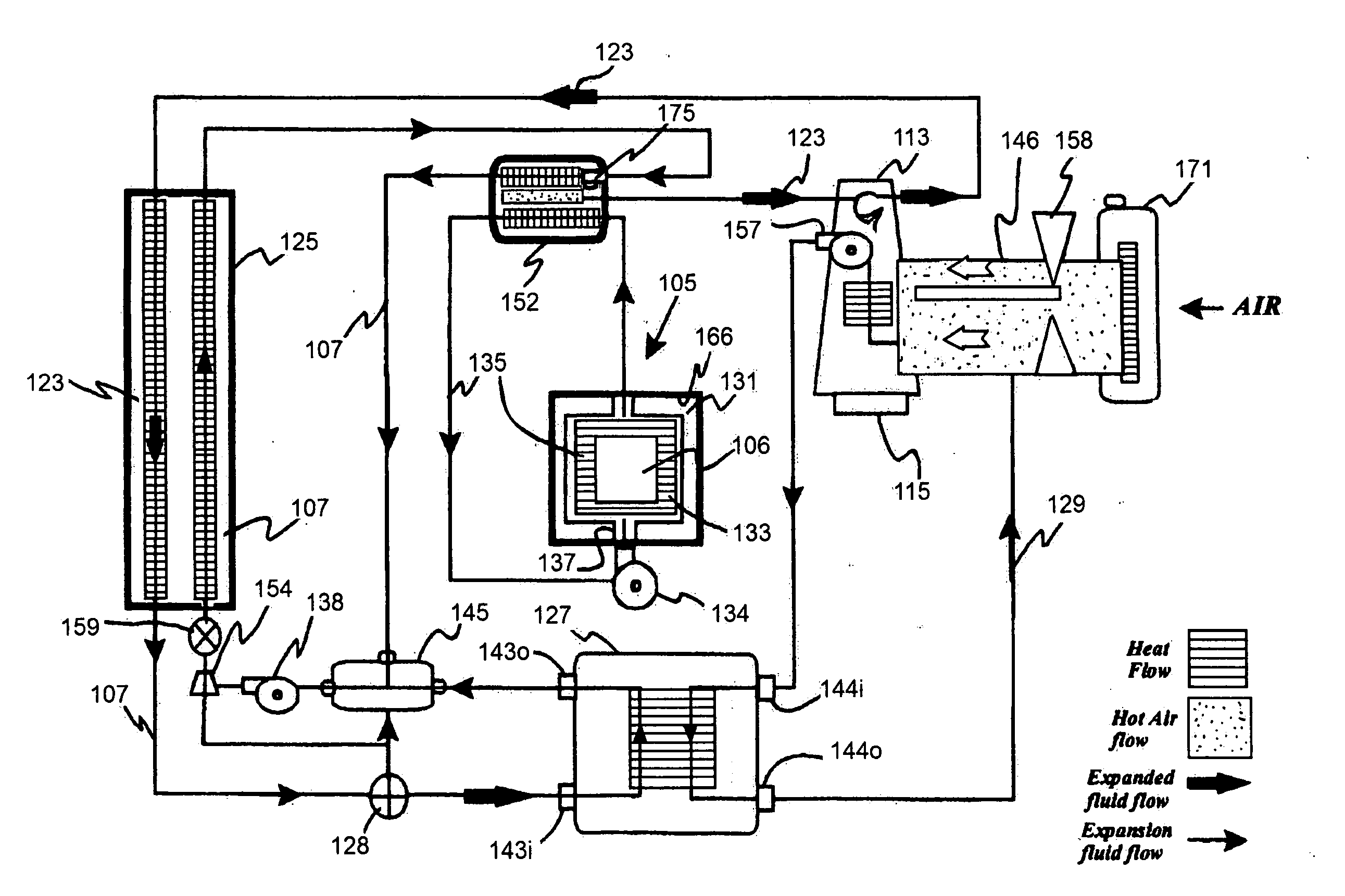
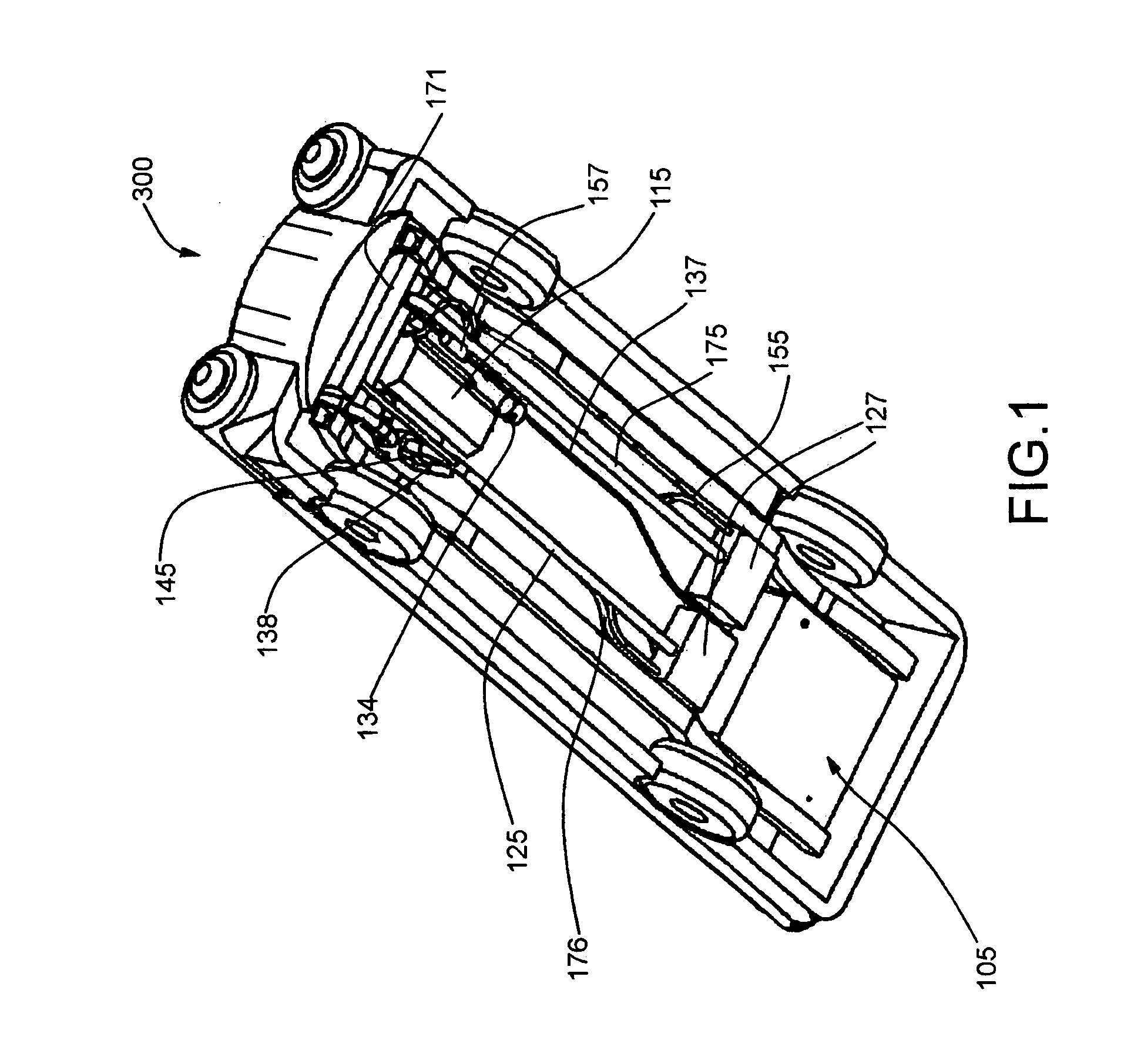
[0120]The present invention relates generally to the field of engines that convert heat into mechanical energy. Referring to FIGS. 1-12, a thermal engine 100 is disclosed which may be used to power a vehicle 300 such as a car or a Train. Thermal engine 100 uses the thermodynamic properties of an expansion fluid 107 and the pressure it generates during phase change to expanded fluid 145 to convert thermal energy to mechanical energy.

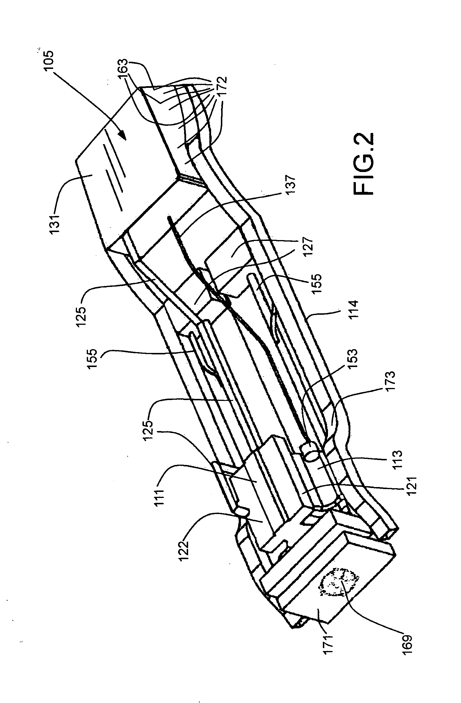
[0121]In its most basic form, as mentioned above generally, the thermal engine 100 incorporates several conventional engine elements including valve cover 111 sealingly mated to valve block 112 sealingly mated to engine block 113 and with a crankcase 114 sealingly mated to sump 115. These components of the thermal engine 100 could be injection molded from suitable engineering plastics and ceramic composites and appropriately lined with durable inserts in areas where wear might be a problem.

[0122]The engine block 113 has one or more longitudinal spaced cyl...


PUM


Abstract

A thermal engine includes an expansion fluid pump which propels water from an expansion fluid tank into an electrolytic cell having an anode and a cathode, which generates a quantity of oxyhydrogen from the water; and propels the oxyhydrogen into one of an engine cylinder and an exhaust chamber, whereupon oxyhydrogen propelled into the cylinder expands abruptly into steam in the intake chamber to increase pressure within the cylinder and thereby enhance thermal engine power, and oxyhydrogen propelled into the heat exchanger cools the water vapor back into liquid water, which generates a vacuum within the exhaust chamber to increase the power of the thermal engine.

Description

FILING HISTORY[0001]This application is a continuation-in-part of application Ser. No. 13 / 506,943 filed on May 25, 2012, which is a continuation-in-part of application Ser. No. 12 / 380,626, filed on Mar. 2, 2009, issuing into U.S. Pat. No. 8,186,160 on May 29, 2012.BACKGROUND OF THE INVENTION[0002]1. Field of the Invention[0003]The present invention relates generally to the field of engines that convert thermal energy into mechanical energy. More specifically the present invention relates to a thermal engine such as for powering a vehicle, and preferably a train or a motorcycle, including a cylinder and a piston having a piston head and a piston crank and an insulated thermal battery including at least a thermal mass such as a metal block for storing and retaining heat to cause expansion fluid to expand inside the a cylinder expansion chamber between the cylinder head and the piston head to drive a crankshaft.[0004]In its most basic form, as mentioned above generally, the thermal eng...

Claims


Application Information

Patent Timeline
IPC IPC(8): F01B17/04C25B1/04F01B23/02F01B23/08F01B31/26
CPCF01B17/04F01B23/02C25B1/04F01B31/26F01B23/08F01B29/06F02B5/00F01K21/02F02B53/02Y02E60/36Y02T10/12
Inventor ANTHONY, MICHAEL, MARK
Owner ANTHONY MICHAEL MARK
Why Eureka
Try Eureka