Accommodating intraocular lens device

a technology of intraocular lens and lens body, which is applied in the field of accommodating intraocular lens body, can solve the problems of changing volume, non-uniform power change, and/or non-uniform buckling of flexible membrane, and achieves the effects of small iol, good optical quality, and constant volum

Active Publication Date: 2016-02-04
LENSGEN INC
View PDF11 Cites 86 Cited by
  • Summary
  • Abstract
  • Description
  • Claims
  • Application Information

AI Technical Summary

Benefits of technology

[0006]The accommodating intraocular lens (IOL) described herein combine the power changing feature of a flexible membrane with a base lens. The power changing feature of the IOL is driven by fluid optics within a closed volume. One significant advantage of the IOL is that the closed volume that spaces apart the flexible membrane and the base lens maintains a substantially constant volume and avoids many of the problems associated with fluid optic IOLs which involve or require a changing volume, i.e., fluid being fed into the chamber from reservoirs. The many disadvantages exhibited by fluid optics requiring changing volumes include non-uniform power change and / or non-uniform buckling of the flexible membrane. The IOLs disclosed herein avoid such problems by maintaining a substantially constant or fixed volume and maintaining good optical quality throughout the range of power change. The fluid redistributes itself within a closed volume as the power changes. This design requires a significantly smaller volume of fluid than known IOL fluid optics that require a reservoir. An additional benefit of this invention by virtue of being a smaller IOL, is a reduction of biocompatibility issues associated with larger IOLs as well as reducing the incision size required to implant the lens. This results in faster healing and a more stable refraction.
[0007]The IOLs disclosed herein may be configured in any number of ways. In one embodiment, the radially compressive forces exerted on an implanted IOL may be concentrated onto the flexible membrane to cause the flexible membrane to change in curvature. At the same time, the IOL is configured such that the radially compressive forces are minimized or reduced with respect to the optic. The optic, however, may be configured to axially displace toward the flexible membrane in response to its change in curvature. This axial displacement may be facilitated by coupling the optic to the peripheral edge of the IOL in a manner that permits the optic to float. As the flexible membrane changes in curvature, fluid adhesion or surface tension will operate to pull the optic toward the flexible membrane. Preferably, the optic resists or does not change in curvature.
[0010]With respect to any of the embodiments, the thickness of the membrane may be uniform or it may be varied. In one embodiment, the membrane may have a thinner central region and a thicker peripheral region, about the central axis A-A, which may permit a larger power change for a given amount of force. However, if the ratio of thicknesses of the central to the peripheral regions of the membrane is too large, significant asphericity may result, reducing the optical quality under compression and making it more difficult to manufacture. A thicker membrane in the center may make it easier to manufacture the IOL but may reduce the potential power change. The determination of the optimal membrane thickness and uniformity of thickness is determined to maximize power change and optical quality while minimizing manufacturing issues and cost. The membrane must also be thick enough to permit handling during the implantation procedure.
[0011]The two-part accommodating IOL devices disclosed herein provides for a number of advantages owing to its separate two-part construction. Implantation of the IOL device requires a significantly reduced incision size, as the two parts of the IOL device are implanted separately and thus significantly reducing the delivery profile for implantation. The reduced incision size provides for a number of advantages, including obviating the need for anesthesia and sutures to close the incision site and improved surgical outcomes.
[0012]Additionally, greater control is afforded with respect to adjusting the sizing and the power of the IOL during surgery. Implanting the base lens assembly into the lens capsule will provide the physician an impression as to the size of the patient's lens capsule and will thus help verify the correct size of the power changing lens that will subsequently be implanted.
[0019]In another embodiment, a two-piece accommodating intraocular lens assembly is described. The two-piece accommodating intraocular lens assembly comprises a base lens assembly and the accommodating IOL described herein. The base assembly comprises a base power optic and a haptic system circumferentially around the base power optic. The haptic system comprises an internal surface facing the base power optic and defining an internal space within which the accommodating IOL is removably maintained.

Problems solved by technology

The many disadvantages exhibited by fluid optics requiring changing volumes include non-uniform power change and / or non-uniform buckling of the flexible membrane.

Method used


Image

  • Accommodating intraocular lens device
  • Accommodating intraocular lens device
  • Accommodating intraocular lens device

Examples


example 1

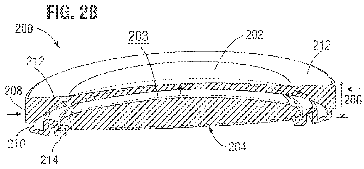
[0089]An IOL similar to the IOL shown in FIG. 2A, except the membrane was 200 microns in the center and 100 microns in the periphery, was modeled with a 7 mm overall diameter and a 1.2 mm center thickness. The modeling included a fluid with a refractive index of 1.49 inside of the closed volume of the IOL. Various modulus materials were modeled and evaluated by finite element analysis. The results demonstrated a power change of 5 D with a 3 mm aperture. The initial diopter power was 22.0 D and the final diopter was 27.2 D.

example 2

[0090]The IOL in Example 1 was built using an optic quality silicone material for the membrane and the closed volume was filled with a silicone fluid having a refractive index of 1.49. Testing was performed with an artificial capsule under similar load configuration in Example 1. The diopter power change measured using a 3 mm aperture was 5.5 D. The power changed from 23 D to 28.5 D with acceptable optical quality throughout the range of power change.

example 3

[0091]The IOL tested in Example 2 was then placed inside of a base lens assembly that was placed inside of an artificial lens capsule. The base lens assembly was similar in design to the lens shown in FIG. 3A. Testing was performed under similar load conditions as Example 2. The base power lens had a −8.5 D power and the power changing lens had a power of 23 D. When the IOL and the base lens assembly were assembled together, the combined power was measured at 14.5 D with a 3 mm aperture. The diopter power change measured using a 3 mm aperture was 5.5 D. The diopter power changed from 14.5 D to 21.0 D with acceptable optical quality throughout the range of power change.


PUM


Abstract

An accommodating intraocular lens (IOL) can be implanted either alone or as part of a two-part lens assembly. The IOL comprises an optic, a flexible membrane and a peripheral edge coupling the optic and the flexible membrane. The peripheral edge comprises an external circumferential surface having a height and a force transmitting area defined along a portion of the height of the external circumferential surface. A closed volume spaces apart the optic and the flexible membrane. The optic is axially displaced and the flexible membrane changes in curvature about a central axis when a radial compressive force is applied to the force transmitting area. A volume defined by the closed volume remains fixed when the optic is axially displaced and the flexible membrane changes in curvature and / or when the radial compressive force is applied to the force transmitting area.

Description

FIELD OF THE INVENTION[0001]The invention relates generally to an accommodating intraocular lens device and, more particularly, to an accommodating intraocular lens device configured for implantation in a lens capsule or suclus of a subject's eye.BACKGROUND[0002]Surgical procedures on the eye have been on the rise as technological advances permit for sophisticated interventions to address a wide variety of ophthalmic conditions. Patient acceptance has increased over the last twenty years as such procedures have proven to be generally safe and to produce results that significantly improve patient quality of life.[0003]Cataract surgery remains one of the most common surgical procedures, with over 16 million cataract procedures being performed worldwide. It is expected that this number will continue to increase as average life expectancies continue to rise. Cataracts are typically treated by removing the crystalline lens from the eye and implanting an intraocular lens (“IOL”) in its pl...

Claims


Application Information

Patent Timeline
Patent Type & Authority Applications(United States)
IPC IPC(8): A61F2/16
CPCA61F2/1635A61F2002/1697A61F2/1648A61F2/1629A61F2250/0018A61F2002/1699A61F2220/0025A61F2002/16901A61F2002/16902A61F2/1694
Inventor BRADY, DANIELSILVESTRINI, THOMASRAO, RAMGOPAL
Owner LENSGEN INC
Why Eureka
Try Eureka