Video-assisted landing guidance system and method

a technology of video assisted landing and guidance system, applied in the direction of image enhancement, process and machine control, instruments, etc., can solve the problems of limited landing area, difficult landing, and stretch the limits of relying on two-dimensional image streams, so as to enable the control of aircraft flight

Inactive Publication Date: 2016-02-04
RAYTHEON CO
View PDF5 Cites 7 Cited by
  • Summary
  • Abstract
  • Description
  • Claims
  • Application Information

AI Technical Summary

Benefits of technology

[0005]The present invention makes use of a stream of video images of a landing site produced during final approach of an aircraft to provide a three-dimensional (3D) mathematical model of the landing site. The 3D model can be used by a remote pilot, thereby providing more than simple two-dimensional images, with the 3D model not being dependent upon clear live images throughout the approach. The 3D model could also be used to provide guidance to an autopilot landing system. All applications of the 3D model can enhance the success of landings in limited landing areas and in poor visibility and poor weather conditions.
[0007]The step of using may include identifying a landing area in a portion of the 3D model of the landing site, and generating signals for enabling control of aircraft flight in response to the updated 3D model and the identified landing area which signals enable the aircraft to land on the identified landing area. The steps of identifying a landing area may use previously known information about the landing site. The method may further comprise receiving azimuth and elevation data of the electro-optic sensor relative to the landing site and using received azimuth and elevation data in the step of calculating relative position and distance data and in the step of generating signals for enabling control of aircraft flight. The landing area may be identified between identified image features. The step of generating signals may provide distance and elevation information between the aircraft and the landing area. The step of generating signals can provide direction and relative velocity information between the aircraft and the landing area.

Problems solved by technology

Landings can be particularly tricky because of transmission delays in the video stream and the resulting control signals needed for adjustments in the last few seconds of landing.
Limited landing areas, such as aircraft carriers and other platforms, stretch the limits of relying on a two dimensional image stream.
Poor weather and visibility increase the difficulty exponentially.
Additional data readings can be provided, however transmission delay issues still remain.
Automated systems might be used, but they can still suffer from delays in collecting and processing information so it can be used for landing.

Method used


Image

  • Video-assisted landing guidance system and method
  • Video-assisted landing guidance system and method
  • Video-assisted landing guidance system and method

Examples


Embodiment Construction

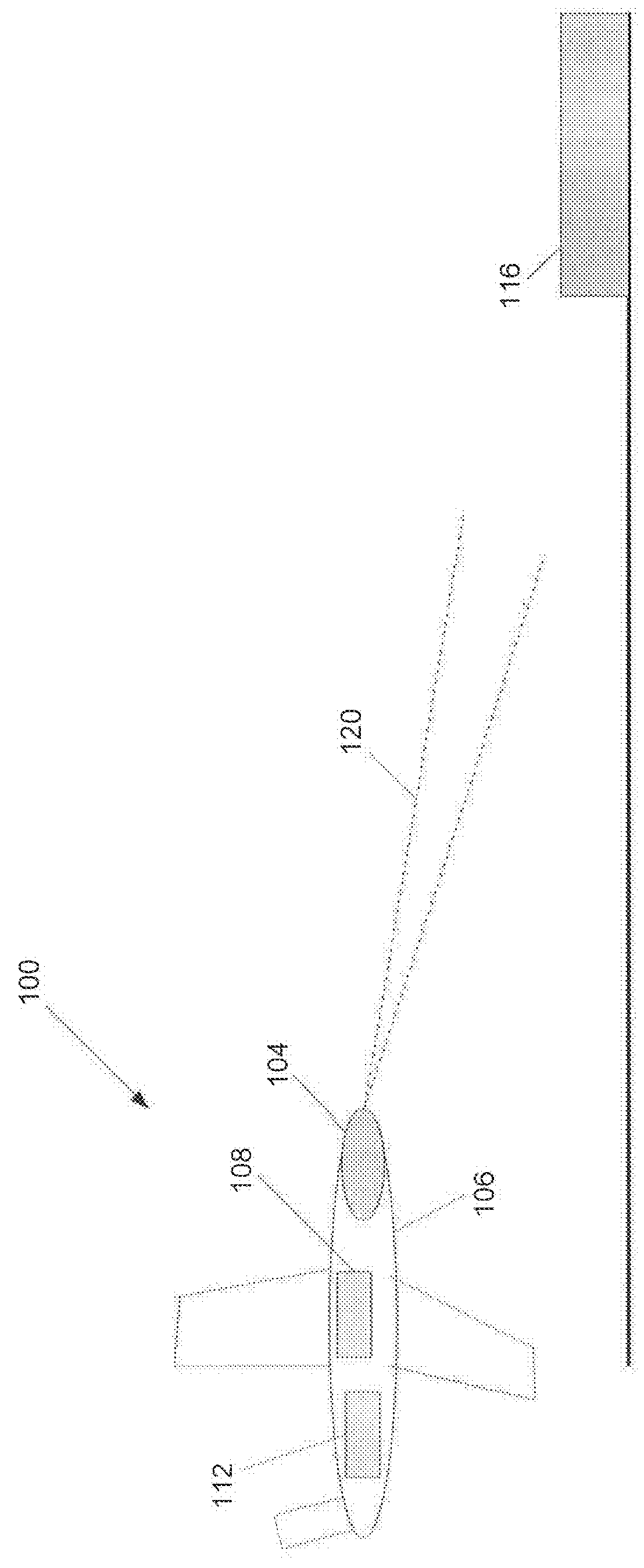
[0024]FIG. 1 is a schematic illustration of a system 100 for aiding landing of an aircraft 106 in the field of view 120 of an imaging sensor 104, according to an illustrative embodiment. In addition to imaging sensor 104, the system 100 can optionally include an inertial measurement unit (IMU) 108 that measures the global-frame three-dimensional position, such as the global positioning system (GPS), of the aircraft 106. The system also includes a computing device 112, that includes a processor to process the video data acquired by the imaging sensor 104 as the aircraft 106 approaches a landing site 116, such as an aircraft carrier, located in the field of view 120 of the imaging sensor 104.

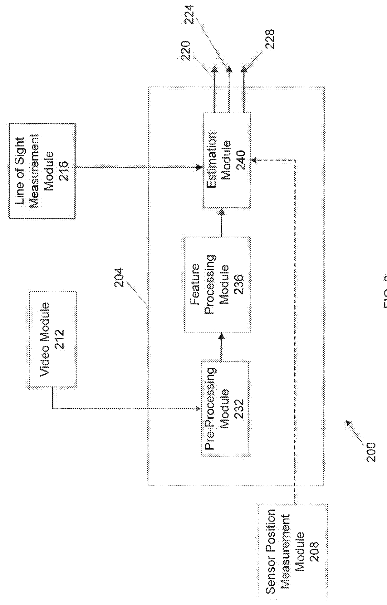
[0025]FIG. 2 is a block diagram 200 of a system for aiding landing of an aircraft, as represented in the schematic of FIG. 1. An image processing module 204 receives data from a video module 212, a line of sight measurement module 216, and optionally from a sensor position measurement module 208. ...


PUM


Abstract

A system and method for aiding landing of an aircraft receives sequential frames of image data of a landing site from an electro-optic sensor on the aircraft; identifies a plurality of features of the landing site in multiple sequential frames of the image data; calculates relative position and distance data between identified features within multiple sequential frames of image data using a local coordinate system within the frames; provides a mathematical 3D model of the landing site in response to the calculated relative position and distance data from the multiple sequential frames; updates the 3D model by repeating the steps of collecting, identifying, and calculating during approach to the landing site by the aircraft; and uses the 3D model from the step of updating for landing the aircraft on the landing site.

Description

FIELD OF THE INVENTION[0001]The present invention generally relates to video-assisted landing guidance systems, and in particular to such systems which are used in unmanned aircraft.BACKGROUND[0002]Unmanned aircraft, or drones, typically use video streams supplied to remote pilots for enabling the pilots to perform flight operations, including landings. Landings can be particularly tricky because of transmission delays in the video stream and the resulting control signals needed for adjustments in the last few seconds of landing. Limited landing areas, such as aircraft carriers and other platforms, stretch the limits of relying on a two dimensional image stream. Poor weather and visibility increase the difficulty exponentially. Additional data readings can be provided, however transmission delay issues still remain. Automated systems might be used, but they can still suffer from delays in collecting and processing information so it can be used for landing.[0003]Accordingly, landing ...

Claims


Application Information

Patent Timeline
Patent Type & Authority Applications(United States)
IPC IPC(8): G06F17/50G05D1/10G06F17/16G06F17/18G06K9/52G06T7/00G06T7/20G06T7/60H04N7/18
CPCG06F17/5004G05D1/101H04N7/18G06T7/0042G06T2200/04G06K9/52G06T7/20G06F17/18G06F17/16G06T7/60G05D1/0684G06T2207/10016G06T2207/10032G06T2207/30252G06T7/579G06T7/246G06T7/277G06V20/64G06V20/176G06F30/13
Inventor MAESTAS, AARONKARLOV, VALERI I.HULSMANN, JOHN D.
Owner RAYTHEON CO
Why Eureka
Try Eureka