Power supply control and current emulation

a voltage regulator and current emulation technology, applied in the field of multiphase voltage regulators, can solve the problems of slow transient response and transient recovery, slow transient response, and slow transient response of conventional voltage regulators operated in such manner, and achieve the effect of reducing the magnitude of the value stored in buffer 170 and preventing errors

Inactive Publication Date: 2016-02-04
INFINEON TECH AMERICAS CORP
View PDF8 Cites 27 Cited by
  • Summary
  • Abstract
  • Description
  • Claims
  • Application Information

AI Technical Summary

Benefits of technology

[0090]By way of one non-limiting example embodiment, the emulator circuit 140 can be configured to reduce a magnitude of the control signal 195 (emulated current flow EMU-IL) by 25% towards 0 Amps. More specifically, at time T71, the computer processing hardware 110 reduces a magnitude of the value stored in buffer 170 by an amount such as 25% of the total magnitude. Additionally, at time T72, the computer processing hardware 110 reduces a magnitude of the value (representing negative current) stored in buffer 170 by an amount such as 25% of the total magnitude.
[0091]In accordance with further embodiments, to ensure that emu_IL (value store

Problems solved by technology

However, conventional voltage regulators operated in such manner typically suffer from relatively slower transient response and transient recovery.
In addition to being complex, such circuits are typically slow to detect actual current flow, especially when implemented in a digital manner.
The delay associated with physically measuring current through the induct

Method used


Image

  • Power supply control and current emulation
  • Power supply control and current emulation
  • Power supply control and current emulation

Examples


Embodiment Construction

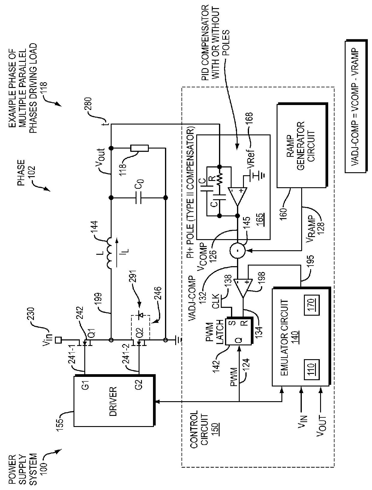
[0038]FIG. 1 is an example diagram of a power supply 100 according to embodiments herein. Note that any or all portions of the logical depiction of control circuit 150 shown in FIG. 1 can be implemented via analog and / or digital components.

[0039]As shown, the power supply 100 includes control circuit 150 (i.e., control circuitry). Controller circuit 150 controls operation of one of multiple phases (such as phase 102) in power supply system 100.

[0040]Note that the power supply system 100 can be configured to include any number of parallel phases. When activated, each phase supplies a corresponding amount of current to power dynamic load 118. Collectively, the sum of currents supplied by the phases power the dynamic load 118. The number of activated phases can vary over time depending on current consumption by dynamic load 118.

[0041]As further shown, phase 102 includes high side switch circuitry 242, low side switch circuitry 246, and inductor 144. Each of the other phases can include...


PUM


Abstract

According to example configurations herein, a power supply control circuit includes an emulator circuit. The emulator circuit includes: i) a first input to receive a first input value, the first input value indicating a magnitude of an input voltage used by a power supply circuit to produce an output voltage to power a respective load, and ii) a second input to receive a second input value, the second input value indicating a magnitude of the output voltage produced by the power supply circuit. The current emulator circuit uses the magnitude of the input voltage and the magnitude of the output voltage to emulate current flowing through the inductor of the power supply circuit. The emulated current flow represents an actual current supplied by the inductor to the load. The power supply control circuit uses the emulated current flowing through the inductor to control the magnitude of the output voltage within a desired range.

Description

RELATED APPLICATIONS[0001]This application is related to and claims the benefit of earlier filed U.S. Provisional Patent Application Ser. No. 62 / 030,307 entitled “Emulated Peak Current Mode Control Scheme,” Attorney Docket No. CHL14-01(IR-2014-04-28a)p, filed on Jul. 29, 2014, the entire teachings of which are incorporated herein by this reference.BACKGROUND[0002]As is well known, conventional multi-phase voltage regulators typically control activation and deactivation of respective control and synchronous switches in a power supply phase to produce an output voltage to power a respective load.[0003]Certain types of voltage regulators, such as those that operate in a current control mode, physically measure an amount of current through a respective inductor of a power supply to control a respective output voltage within a desired range. In general, power supplies that operate in accordance with a current control mode measure an error voltage as well measure an actual current through...

Claims


Application Information

Patent Timeline
IPC IPC(8): H02M3/158
CPCH02M3/158H02M1/0029H02M1/0009
Inventor SREENIVAS, VENKAT
Owner INFINEON TECH AMERICAS CORP
Why Eureka
Try Eureka