Hematology systems and methods

a technology of hematology and systems, applied in the field of hematology systems and methods, to achieve the effect of high viscosity and high viscosity

Active Publication Date: 2016-02-11
IRIS INT
View PDF22 Cites 15 Cited by
  • Summary
  • Abstract
  • Description
  • Claims
  • Application Information

AI Technical Summary

Benefits of technology

[0012]The PIOAL aligns non-spherical particles in a plane substantially parallel to the flow direction, which results in image optimization. The PIOAL also assists spherical cells in positioning, repositioning and / or better-positioning of intracellular structures, organelles or lobes substantially parallel to the direction of flow. In some embodiments, platelets, reticulocytes, nucleated RBCs, and WBCs, including neutrophils, lymphocytes, monocytes, eosinophils, basophils, and immature WBCs including blasts, promyelocytes, myelocytes, or metamyelocytes are counted and analyzed as particles.
[0075]In another aspect, embodiments of the present invention encompass methods of imaging particles in a sample. Exemplary methods can include providing a visual analyzer for a sample comprising particles suspended in a liquid, establishing a flow having laminar sections that are of higher and lower viscosity in the visual analyzer. The analyzer can include a flowcell coupled to a source of the sample and to a source of a PIOAL having a higher viscosity than the viscosity of the sample. The flowcell can define an internal flowpath, and can direct a flow of the sample enveloped with the PIOAL through a viewing zone in the flowcell. The analyzer can also include a high optical resolution imaging device with an objective on an optical axis that intersects the ribbon-shaped sample stream, a relative distance between the high optical resolution imaging device and the flowcell being variable by operation of a motor drive, for resolving and collecting a digitized image on a photosensor array. The analyzer can also include an autofocus pattern having a position fixed relative to the flowcell, the autofocus pattern being located at a displacement distance from the plane of the ribbon-shaped sample stream that has been predetermined, a light source configured to illuminate the ribbon-shaped sample stream and the autofocus pattern, at least one digital processor coupled to operate the motor drive and to analyze the digitized image, where the processor is configured to determine a focus position of the autofocus pattern and to relatively displace the high optical resolution imaging device and the flowcell over the displacement distance from the focused position, whereby the high optical resolution imaging device becomes focused on the ribbon-shaped sample stream. In some cases, an analyzer can include a flowcell coupled to a source of the sample and to a source of a PIOAL where the flowcell defines an internal flowpath and is configured to direct a flow of the sample enveloped with the PIOAL through a viewing zone in the flowcell, a high optical resolution image device with an objective on an optical axis that intersects the ribbon-shaped sample stream, a relative distance between the objective and the flowcell being variable by operation of a motor drive, for resolving and collecting a digitized image on a photosensor array, an autofocus pattern having a position fixed relative to the flowcell, the autofocus pattern being located at a displacement distance from the plane of the ribbon-shaped sample stream that has been predetermined, a light source configured to illuminate the ribbon-shaped sample stream and the autofocus pattern, and at least one digital processor coupled to operate the motor drive and to analyze the digitized image, where the processor is configured to determine a focus position of the autofocus pattern and to relatively displace the high optical resolution imaging device and the flowcell over the displacement distance from the focused position, whereby the high optical resolution imaging device becomes focused on the ribbon-shaped sample stream.

Problems solved by technology

Such techniques overcome certain difficulties associated with conventional sheath fluids used in flow cytometry that may suffer from the disadvantages of maintaining cell morphology and / or not providing for the capture of optimized images which permit determination of one or more blood components.

Method used


Image

  • Hematology systems and methods
  • Hematology systems and methods
  • Hematology systems and methods

Examples


examples

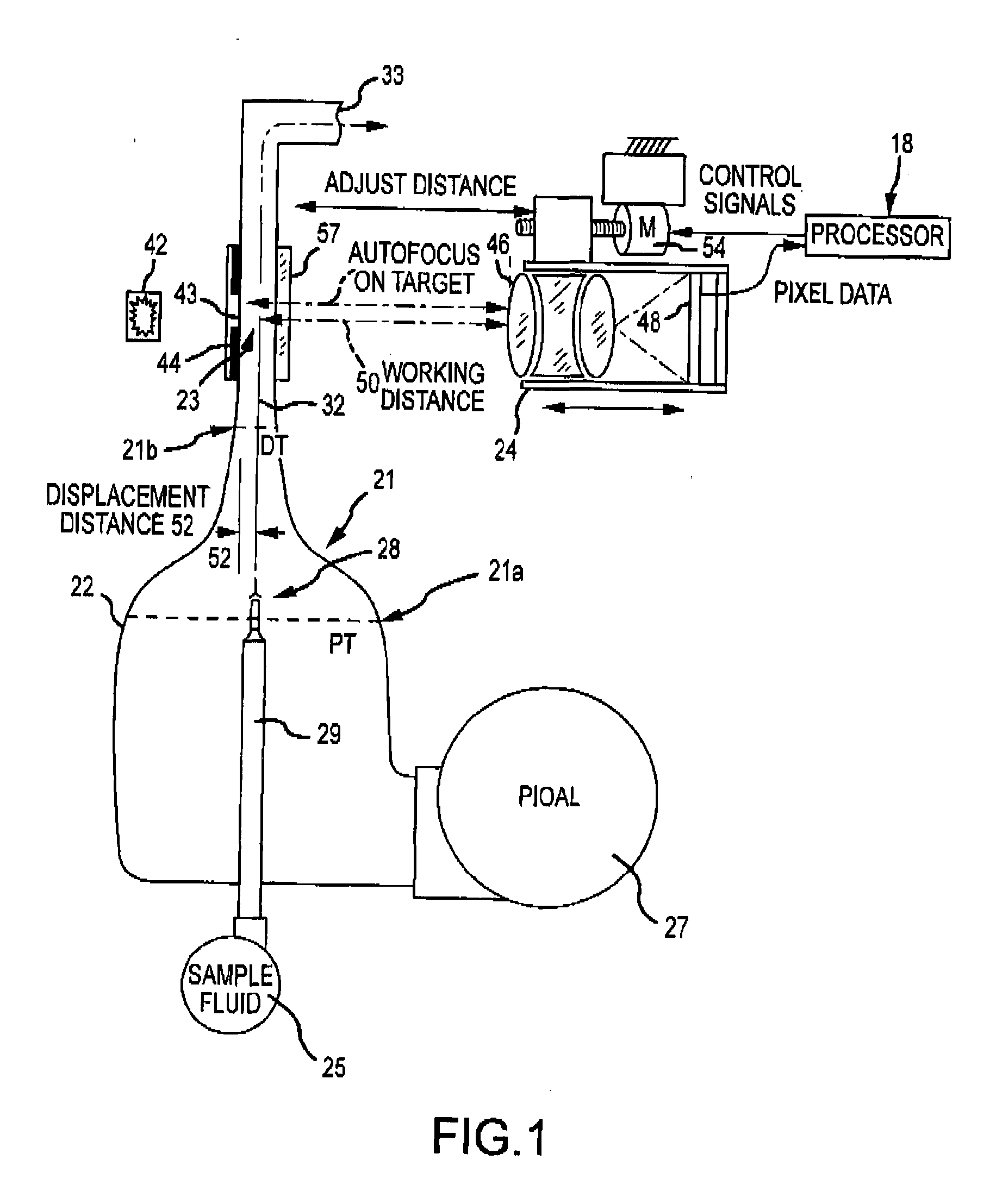
[0285]Any of a variety of hematology or blood particle analysis techniques can be performed using images of sample fluid flowing through the flowcell. Often, image analysis can involve determining certain cell or particle parameters, or measuring, detecting, or evaluating certain cell or particle features. For example, image analysis can involve evaluating cell or particle size, cell nucleus features, cell cytoplasm features, intracellular organelle features, and the like. Relatedly, analysis techniques can encompass certain counting or classification methods or diagnostic tests, including white blood cell (WBC) differentials. In some cases, images obtained using the flowcell can support a 5-part WBC differential test. In some cases, images obtained using the flowcell can support a 9-part WBC differential test. Relatedly, with reference to FIG. 4, the processor 440 can include or be in operative association with a storage medium having a computer application that, when executed by t...


PUM

PropertyMeasurementUnit
viscosityaaaaaaaaaa
viscosityaaaaaaaaaa
viscosityaaaaaaaaaa

Abstract

Aspects and embodiments of the instant disclosure provide a particle and / or intracellular organelle alignment agent for a particle analyzer used to analyze particles contained in a sample. An exemplary particle and / or intracellular organelle alignment agent includes an aqueous solution, a viscosity modifier, and / or a buffer. Embodiments also encompass systems, compositions, and methods for analyzing a sample containing particles. Particles such as blood cells can be categorized and counted by a digital image processor. A digital microscope camera can be directed, for example using certain focusing techniques, into a flowcell defining a symmetrically narrowing flowpath in which the sample stream flows in a ribbon flattened by flow and viscosity parameters between layers of sheath fluid. Blood cell images can be collected and analyzed using dynamic range extension processes and systems.

Description

CROSS-REFERENCES TO RELATED APPLICATIONS[0001]This application is a non-provisional of, and claims the benefit of priority to, U.S. Provisional Patent Application No. 61 / 799,152 filed Mar. 15, 2013, the content of which is incorporated herein by reference. This application is also related to U.S. patent application Ser. Nos. 14 / 215,834, 14 / 216,533, 14 / 216,339, 14 / 216,811 and 14 / 217,034; and International Patent Application Nos. (flowcell, autofocus, sheath fluid, dynamic range, contrast agent), all filed Mar. 17, 2014. The content of each of these filings is incorporated herein by reference.BACKGROUND OF THE INVENTION[0002]This disclosure relates to the field of apparatus, systems, compositions, and methods for analysis of particles, including imaging of particles in fluid samples, using wholly or partly automated devices to discriminate and quantify particles such as blood cells in the sample. The present disclosure also relates to a particle and / or intracellular organelle alignmen...

Claims


Application Information

Patent Timeline
Patent Type & Authority Applications(United States)
IPC IPC(8): G01N15/14G01N33/49
CPCG01N15/1404G01N2015/1486G01N2015/1413G01N33/49G01N2015/1452G01N15/1468G01N2015/0065G01N2015/1037G01N2015/1411G01N15/1434G01N15/147G01N15/1463G01N15/1475G01N21/53G01N2021/058G01N1/30G01N33/4915G01N33/5094G01N15/06G01N15/1459G01N15/1429G01N2015/1481G02B21/244G06T7/0012G06T2207/10148G02B7/28G01N2015/144G01N15/1436G02B7/36G01N33/5091G01N33/80
Inventor WANDERS, BART J.FARRELL, GREGORY A.ADAMS, THOMAS H.GRONER, WARRENZHAO, XIAODONGJORDAN, BRETTCREMINS, JACKQUON, CAROL
Owner IRIS INT
Why Eureka
Try Eureka