Optical system and assay chip for probing, detecting and analyzing molecule
Active Publication Date: 2016-02-11
QUANTUM SI
View PDF5 Cites 155 Cited by
Summary
Abstract
Description
Claims
Application Information
AI Technical Summary
This helps you quickly interpret patents by identifying the three key elements:
Problems solved by technology
Method used
Benefits of technology
[0033]The phrase “enhance excitation energy” may be used in the present disclosure to refer to increasing an intensity of excitation energy at an excitation region of a sample well. The intensity may be increased by concentrating and/or resonating excitation energy incident on the sample well, for example. In some cases, the intensity may be increased by anti-reflective coatings or lossy layers that allow the excitation energy to penetrate further into the excitation region of a sample well. An enhancement of excitation energy may be a comparative reference to an embodiment that does not include structures to enhance the excitation energy at an excitation region of a sample well.
[0034]The terms “about,”“approximately,” and “substantially” may be used in the present disclosure to refer to a value, and are intended to encompass the referenced value plus and minus acceptable variations. The amount of var
Problems solved by technology
Bioassays conventionally involve large, expensive laboratory equipment requiring research scientists trained to operate the equipment and perform the bioassays.
Bioassays using luminescent ta
Method used
Image
Click on the blue label to locate the original text in one second.
Reading with bidirectional positioning of images and text.
Examples
Embodiment Construction
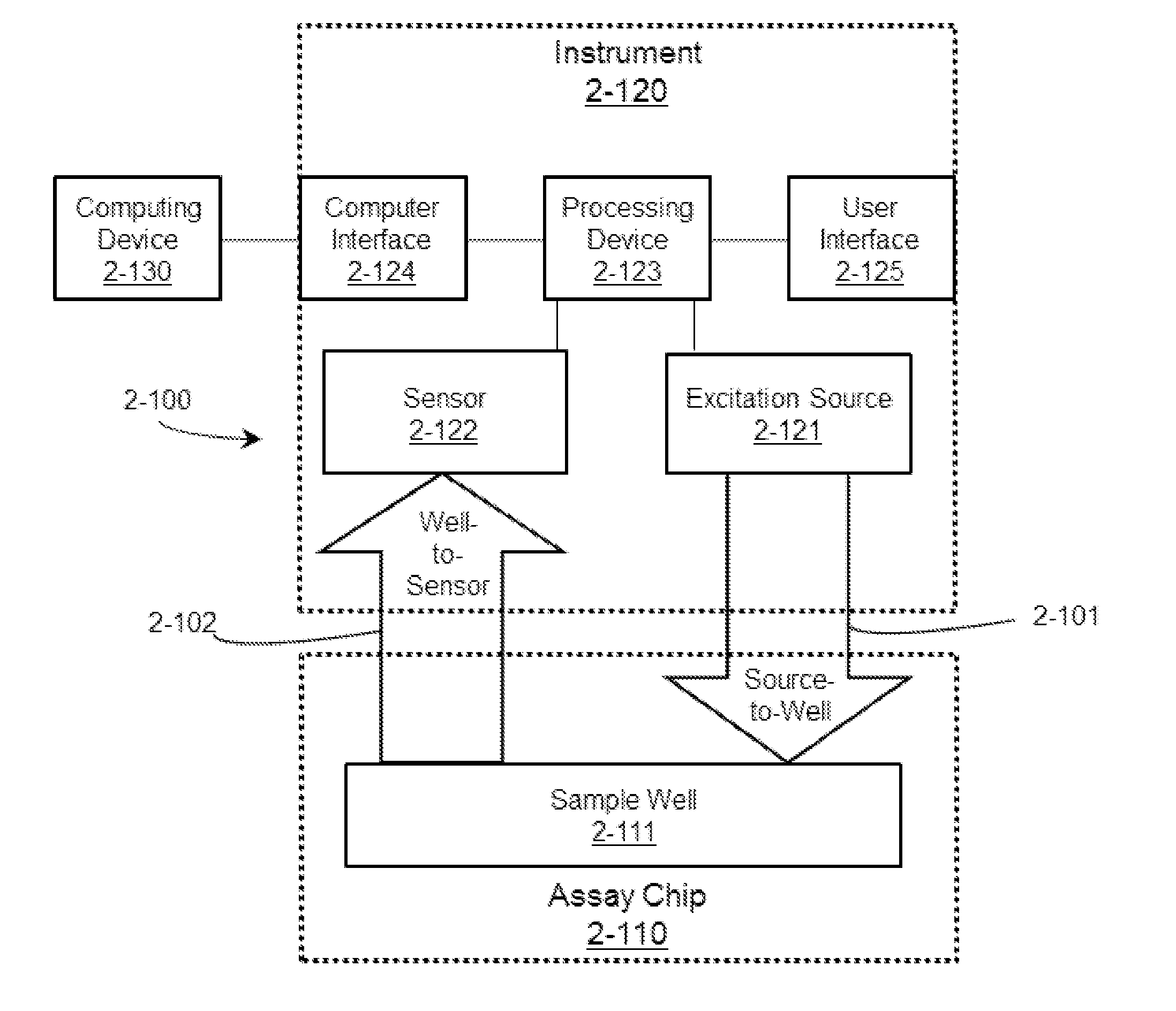
[0197]The inventors have recognized and appreciated that conventional apparatuses for performing bioassays are large, expensive and require advanced laboratory techniques to perform. Many types of bioassays depend on the detection of single molecules in a specimen. Conventionally single molecule detection may require large, bulky laser systems used to generate high intensity light needed for excitation of molecules. In addition, bulky optical components may be used to direct the laser light to the specimen and additional optical components may be used to direct luminescent light from the specimen to a sensor. These conventional optical components may require precise alignment and stabilization. The conventional laboratory equipment and training required to use this conventional equipment may result in complex, expensive bioassays.
[0198]The inventors have recognized and appreciated that there is a need for a device that can simply and inexpensively analyze biological and / or chemical ...
PUM
Property
Measurement
Unit
Distance
aaaaa
aaaaa
Distance
aaaaa
aaaaa
Distance
aaaaa
aaaaa
Abstract
Apparatus and methods for analyzing single molecule and performing nucleic acid sequencing. An apparatus can include an assay chip that includes multiple pixels with sample wells configured to receive a sample, which, when excited, emits emission energy; at least one element for directing the emission energy in a particular direction; and a light path along which the emission energy travels from the sample well toward a sensor. The apparatus also includes an instrument that interfaces with the assay chip. The instrument includes an excitation light source for exciting the sample in each sample well; a plurality of sensors corresponding the sample wells. Each sensor may detect emission energy from a sample in a respective sample well. The instrument includes at least one optical element that directs the emission energy from each sample well towards a respective sensor of the plurality of sensors.
Description
RELATED APPLICATIONS[0001]This application claims priority to U.S. Provisional Patent Application 62 / 035,242, entitled “OPTICAL SYSTEM AND ASSAY CHIP FOR PROBING, DETECTING AND ANALYZING MOLECULES,” filed Aug. 8, 2014, which is hereby incorporated by reference in its entirety.[0002]This application is related to the following U.S. applications:[0003]U.S. Provisional Patent Application 62 / 164,506, entitled “INTEGRATED DEVICE FOR TEMPORAL BINNING OF RECEIVED PHOTONS”, filed on May 20, 2015;[0004]U.S. Provisional Patent Application 62 / 164,485, entitled “PULSED LASER”, filed on May 20, 2015;[0005]U.S. Provisional Patent Application 62 / 164,482, entitled “METHODS FOR NUCLEIC ACID SEQUENCING”, filed on May 20, 2015;[0006]U.S. Provisional Patent Application 62 / 164,464, entitled “INTEGRATED DEVICE WITH EXTERNAL LIGHT SOURCE FOR PROBING DETECTING AND ANALYZING MOLECULES”, filed on May 20, 2015;[0007]A U.S. non-provisional patent application filed on even date herewith, bearing docket no. R070...
Claims
Application Information
Patent Timeline
Application Date:The date an application was filed.
Publication Date:The date a patent or application was officially published.
First Publication Date:The earliest publication date of a patent with the same application number.
Issue Date:Publication date of the patent grant document.
PCT Entry Date:The Entry date of PCT National Phase.
Estimated Expiry Date:The statutory expiry date of a patent right according to the Patent Law, and it is the longest term of protection that the patent right can achieve without the termination of the patent right due to other reasons(Term extension factor has been taken into account ).
Invalid Date:Actual expiry date is based on effective date or publication date of legal transaction data of invalid patent.
Inventor ROTHBERG, JONATHAN M.KABIRI, ALISICKLER, JASON W.GYARFAS, BRETT J.LACKEY, JEREMYSCHMID, GERARDGLENN, PAUL E.WEST, LAWRENCE C.CIPRIANY, BENJAMINFIFE, KEITH G.