Microcomputer

a microcomputer and microprocessor technology, applied in the field of microcomputers, can solve the problems of less likely to be used and accelerate the data transfer process, and achieve the effect of accelerating the data transfer

Active Publication Date: 2016-02-18
RENESAS ELECTRONICS CORP
View PDF1 Cites 0 Cited by
  • Summary
  • Abstract
  • Description
  • Claims
  • Application Information

AI Technical Summary

Benefits of technology

[0030]According to the above-described one embodiment, the advantage of a data transfer apparatus in which data transfer information is stored on a general storage apparatus (RAM) is maintained. Thus, various reque

Problems solved by technology

Accordingly, in the case where a plurality of activation factors occur at similar frequencies, data tra

Method used


Image

  • Microcomputer
  • Microcomputer
  • Microcomputer

Examples


first embodiment

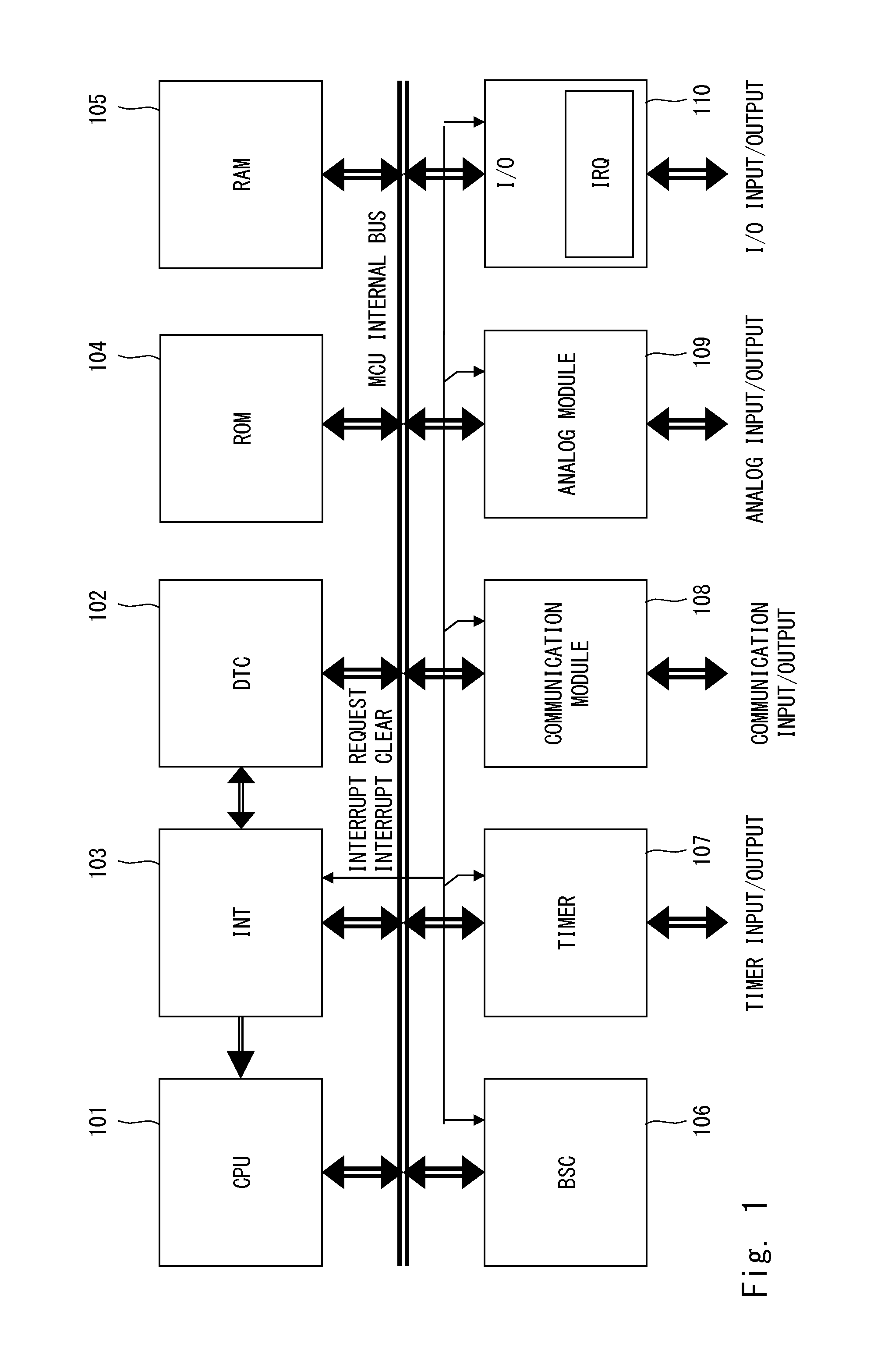
[0080]Firstly, a description will be given of the configuration of a microcomputer (MCU) 100 according to a first embodiment with reference to the block diagram of FIG. 1.

[0081]The MCU 100 is configured by a central processing unit (CPU) 101, a data transfer controller (DTC) 102, an interrupt controller (INT) 103, read-only memory (ROM) 104, random-access memory (RAM) 105, a bus controller (BSC) 106, a timer 107, a communication module 108 such as a serial communication interface, an analog module 109 such as an A / D converter and a D / A converter, an input / output port (I / O) 110, and not-shown functional blocks or modules of reset control, operation mode control and the like. These are connected to one another by an MCU internal bus (master and slave buses).

[0082]In the MCU 100, the CPU 101 principally performs operations. The CPU 101 reads instructions mainly from the ROM 104 and operates accordingly. The DTC 102 performs data transfer in place of the CPU 101 based on the setting of ...

second embodiment

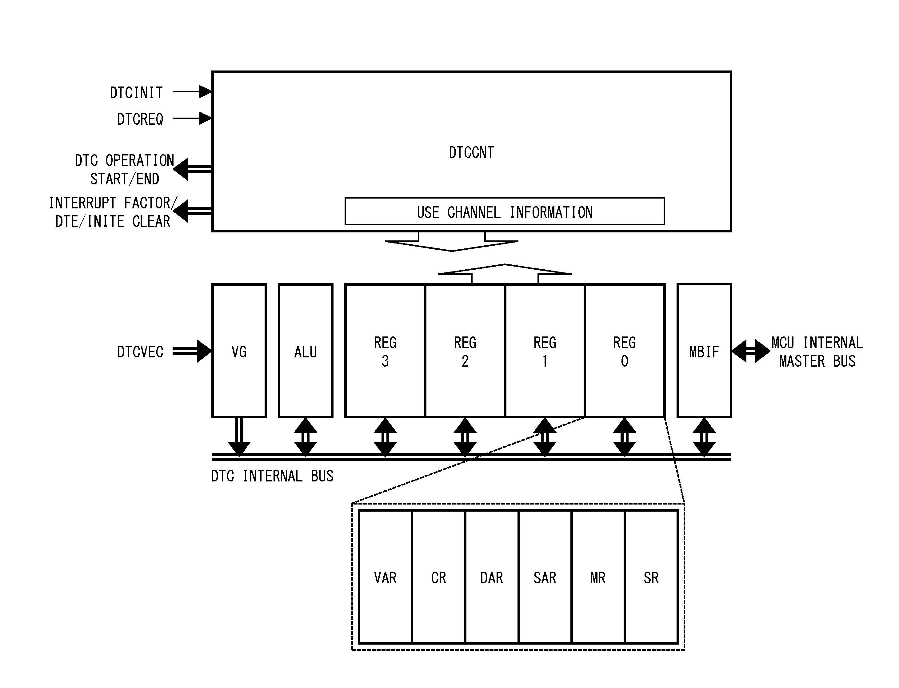
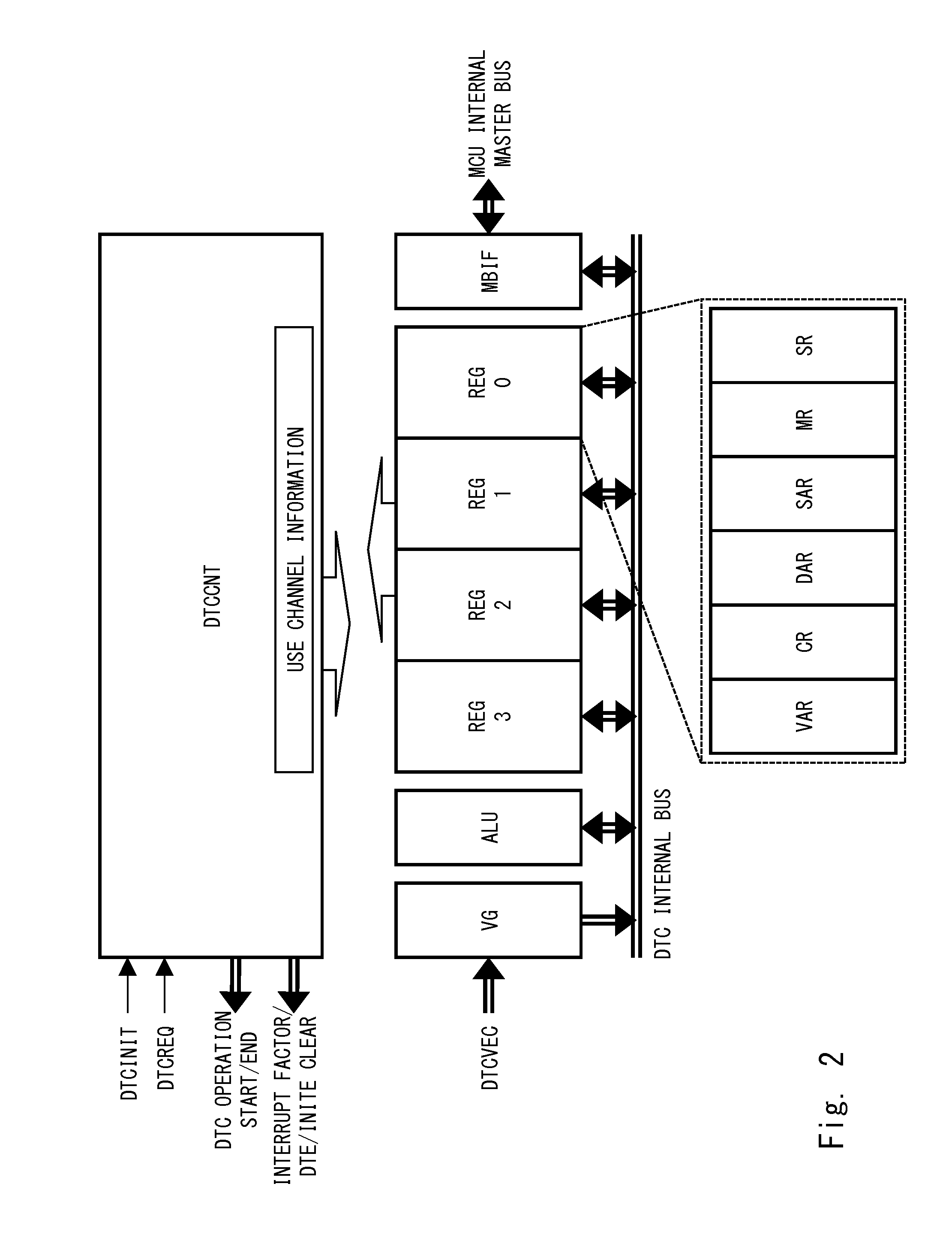
[0161]FIG. 10 shows a register file and data transfer information (a transfer information set) of a DTC 102 according to a second embodiment.

[0162]The second embodiment is different from the first embodiment in the configuration of the status register (SR). The bit configuration of the SR is as follows.

[0163]Bits 27 to 2 are a data transfer information starting address. The data transfer information is in a 32-bit (long word) unit, and low-order 2 bits are regarded as 00.

[0164]Bit 0 is a VLD flag, and represents that the data transfer information held by the pertinent register file is valid. Bit 0 is cleared to 0 by reset. Bit 0 is set to 1 when data transfer information is stored on the pertinent register file. Bit 0 is cleared to 0 when execution of prescribed data transfer has finished.

[0165]When the address space of the CPU is smaller than 4 GB, or when the address space in which data transfer information can be arranged can be reduced, it is possible to provide PRM and LRU flag...

third embodiment

[0209]FIG. 16 shows a register file and data transfer information (a transfer information set) of a DTC 102 according to a third embodiment.

[0210]In the present embodiment, bits 31 and 30 of the mode register (MR) are AUTE and AUTS bits.

[0211]When the AUTE bit is set to 1, the DTCCNT successively performs data transfer for the number of times specified by the CR. The AUTS bit specifies whether to hand over the bus right to the CPU midway through the successive execution.

[0212]FIG. 17 shows a state transition diagram of the DTC 102 according to the third embodiment.

[0213]When the DCTCNT is provided with DTCINT, the state transits to a vector IR state.

[0214]S702 (IR state): When transition to the IR state has been triggered by DTCINT, the DCTCNT reads data transfer information stored in the data transfer information arrange area. When the AUTE bit of the read MR is cleared to 0, the state returns to the stop state. When the AUTE bit is set to 1, the state subsequently transits to the ...


PUM


Abstract

A microcomputer includes: a central processing unit (CPU); a data transfer apparatus (DTC); and a storage apparatus (RAM). The data transfer apparatus includes a plurality of register files each including a mode register storing the transfer mode information, an address register to which the address information is transferred, and a status register (SR) representing information that specifies the transfer information set. The data transfer apparatus checks the information of the status register, to determine whether to use the transfer information set held in the register files or to read the transfer information set from the storage apparatus and to rewrite a prescribed one of the register files. The data transfer apparatus performs data transfer based on the transfer information set stored in one of the register files.

Description

CROSS-REFERENCE TO RELATED APPLICATIONS[0001]This application is based upon and claims the benefit of priority from Japanese patent application No. 2014-165636, filed on Aug. 18, 2014, the disclosure of which is incorporated herein in its entirety by reference.BACKGROUND[0002]The present invention relates to a microcomputer. Specifically, the present invention relates to a data transfer technique that can be applied to a microcomputer having, for example, a central processing function and a data transfer function.TECHNICAL BACKGROUND[0003]As disclosed in “LSI handbook” (The Institute of Electronics, Information and Communication Engineers: IEICE, Ohm-sha Ltd. Japan, pp. 540-541, November, 1984), a single-chip microcomputer consists of a single semiconductor substrate, on which functional blocks such as a central processing unit (CPU) being the core element, ROM (read-only memory) for holding a program, RAM (random-access memory) for holding data, and an input / output circuit for rece...

Claims


Application Information

Patent Timeline
IPC IPC(8): G06F9/30G06F12/06G06F13/24
CPCG06F9/30058G06F13/24G06F2212/657G06F9/30189G06F12/0653G06F13/26G06F13/28G06F13/385Y02D10/00G06F9/30098
Inventor MITSUISHI, NAOKIIKARI, SEIJI
Owner RENESAS ELECTRONICS CORP
Why Eureka
Try Eureka