Thermally efficient portable vaporizer heating assembly

a vaporizer and portable technology, applied in the field of vaporizers, can solve the problems of cumbersome assembly or casing, not easy to carry, cumbersome vaporization process, and inability to effectively and conveniently transport devices, and achieve the effect of improving the thermal efficiency of the vaporizer heating assembly

Inactive Publication Date: 2016-02-25
VAPORFECTION INT
View PDF0 Cites 41 Cited by
  • Summary
  • Abstract
  • Description
  • Claims
  • Application Information

AI Technical Summary

Benefits of technology

[0026]In accordance with the present invention, a method of improving a thermal efficiency of a vaporizer heating assembly having a glass airflow passage is disclosed. The method includes providing a vaporizer heating assembly having a glass body defining an airflow passage, a heating element thermally coupled to the glass body, and a material placement zone downstream from the airflow passage. A thermally conductive layer is applied to at least a portion of an outer surface of the glass body.

Problems solved by technology

For most known vaporizers, the vaporization process requires an assembly or casing that is cumbersome and not easily portable.
Those assemblies that are portable are too large to conceal within a standard-sized pant pocket and do not allow the device to be effectively and conveniently transported.
Most of these vaporizes also require the unit to be plugged in to an electric outlet, which is inconvenient for those persons without access to electricity.
There are numerous disadvantages associated with the elongated shape of the vaporizer.
With the mouthpiece coupled to the end of the device it becomes readily identifiable as a smoking-type apparatus, which many users find undesirable.
Few, if any, of those hand-held vaporizers easily conceal the mouth piece, without removal into multiple components, which can be easily misplaced and / or dropped.
As most mouth pieces are not easily concealable, and because they generally have at least one opening disposed to the outside environment to inhale the vapor, the device also becomes susceptible to liquids and debris from entering, which may contaminate the device's functionality.
Those vaporizers that are shaped in an elongated fashion also typically require the vaporizer to be subject to the time-intensive task of disassembling it into multiple components in order for the user to insert the herbs.
As such, few vaporizers allow a user to insert and remove herbs into the vapor chamber quickly and efficiently without at least partially disassembling the device.
This, however, negatively creates an inconsistent temperature at the mouthpiece that is dependent on the inhaling rate of the user.
This can lead to a less effective release of the active ingredients in the herbs, should the user inhale very fast.
Furthermore, as the temperature generally varies, depending on the inhaling rate, many hand-held vaporizers require a user to inconveniently adjust their breathing rate to produce the desired temperature at the mouth piece.
As the temperature generally varies, most known portable hand-held vaporizers do not allow the user to have an optimized air flow, a safe vapor temperature at the mouth piece, and a highly potent vapor containing the herb's active ingredients.
Conduction vaporizers have their own set of problems, however, and are generally considered inferior to convection-based heated vaporizers.
Prior-art vaporizers use a heating element, typically a metallic heating element, that adds an unpleasant taste to the air stream flowing through it.
This unpleasant, contaminated, metallic taste takes away from the enjoyment, i.e. the user experience, of the vaporizing process.
In addition, prior art vaporizers are made with a heating element inside an air-flow conduit where the heating element rests against a portion of the interior of the conduit, thereby preventing air from flowing around certain portions of the heating element, resulting in non-optimized airflow and / or heat exchange.
Many vaporizers are not thermally efficient, which is particularly troublesome with portable vaporizers that require high energy efficiency for optimal battery power life.
For example, some prior-art vaporizers utilize materials, such as metal components, that absorb a large amount of heat, thus, requiring the expenditure of additional energy to generate optimum heat levels.
For example, certain portions of the portable vaporizer, such as electronic components, do not operate, or operate at lesser efficiencies, when exposed to high temperatures from the heating element.
Additionally, selecting proper materials and configurations for a portable vaporizer can be challenging, particularly where size considerations, power considerations, and user experience considerations are in tension with one another.

Method used


Image

  • Thermally efficient portable vaporizer heating assembly
  • Thermally efficient portable vaporizer heating assembly
  • Thermally efficient portable vaporizer heating assembly

Examples


Embodiment Construction

[0049]While the specification concludes with claims defining the features of the invention that are regarded as novel, it is believed that the invention will be better understood from a consideration of the following description in conjunction with the drawing figures, in which like reference numerals are carried forward. It is to be understood that the disclosed embodiments are merely exemplary of the invention, which can be embodied in various forms.

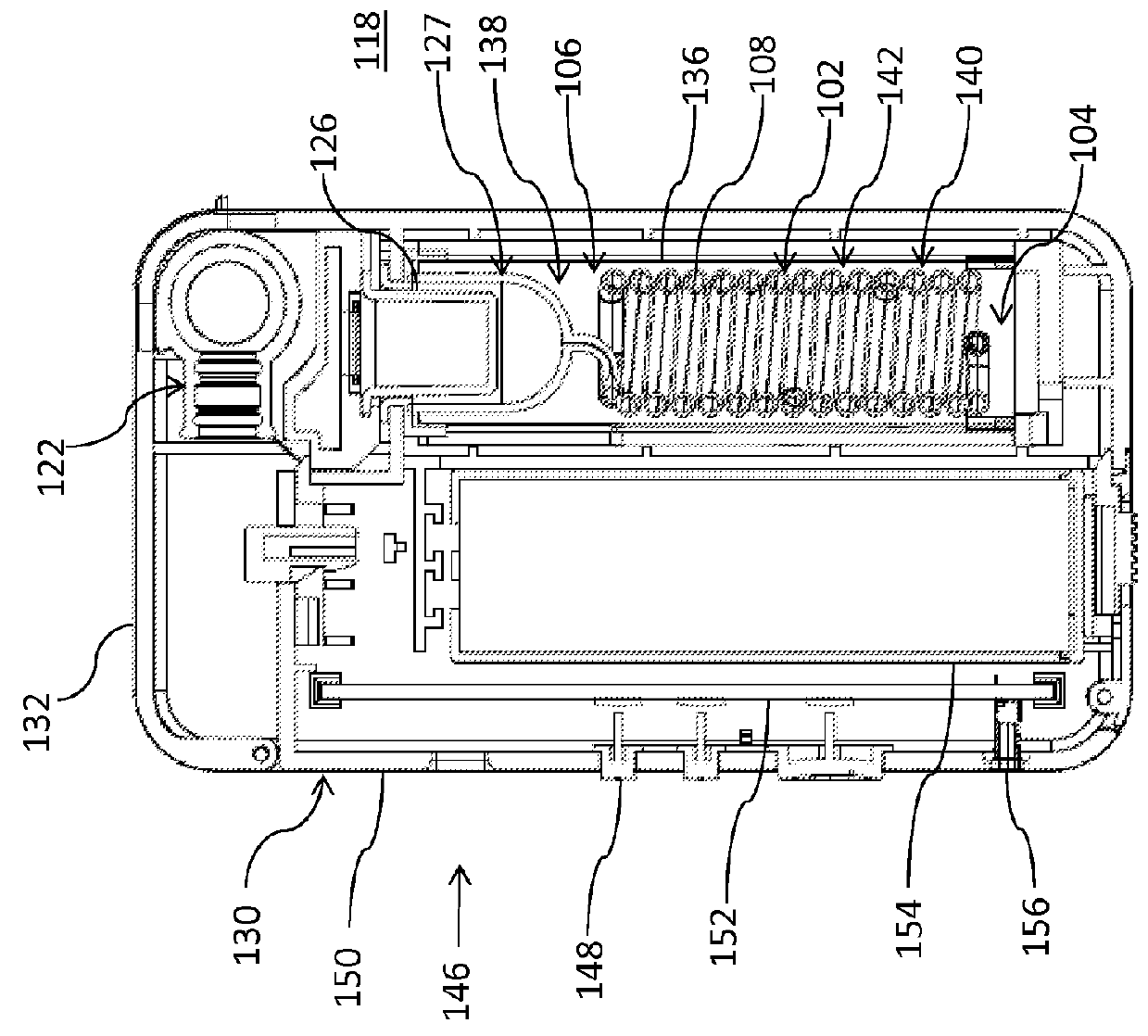
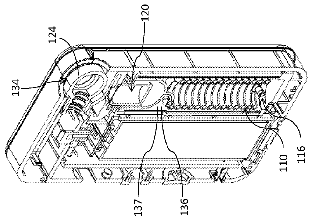
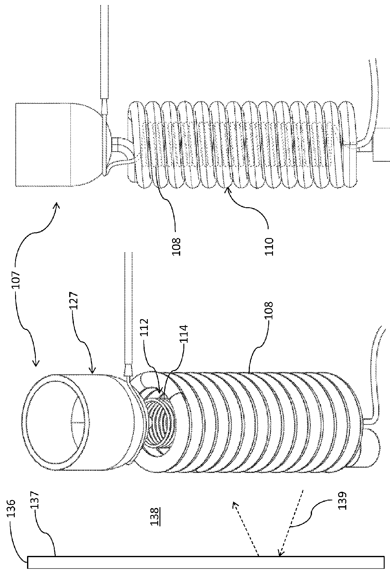
[0050]The present invention provides a novel and efficient portable hand-held vaporizer assembly that provides a glass spiral airflow chamber coated with a thermally conductive boron nitride layer to reduce a thermal inertia of the glass spiral airflow chamber. In addition, embodiments of the invention provide for impregnating the wall surrounding the airflow chamber with a thermally reflective copper-nickel substance to reflect heat radiating from the heat engine, thereby conserving thermal energy.

[0051]Referring now to FIGS. 1-4, one...


PUM

PropertyMeasurementUnit
vapor temperatureaaaaaaaaaa
lengthaaaaaaaaaa
lengthaaaaaaaaaa

Abstract

A portable hand-held vaporizer assembly having a glass body defining an airflow passage is disclosed. A heating element is thermally coupled to the glass body and a material placement zone is downstream from the airflow passage. Furthermore, a thermally conductive layer covers at least a portion of an outer surface of the glass body and a thermally reflective substance is included with walls encapsulating the glass body and the heating element.

Description

FIELD OF THE INVENTION[0001]The present invention relates generally to a vaporizer for inhalation of active ingredients within a plant material, and more particularly relates to a portable, concealable, hand-held, vaporizer utilizing convection heating and a spiral airflow chamber, including a thermally conductive layer and a thermally reflective layer to reduce thermal inefficiencies.BACKGROUND OF THE INVENTION[0002]A vaporizer is a device used to extract the active ingredients of plant material, e.g., tobacco, or other herbs or blends, for inhalation by a human. Vaporization involves heating a material so that its active compounds boil off into a vapor. As opposed to smoking, i.e., burning, vaporization avoids the production of irritating, toxic, and carcinogenic by-products. In fact, no combustion occurs, so no smoke or taste of smoke is present. Studies show that vapor contains substantially zero particulate matter or tar, and, in comparison to smoking, significantly lower conce...

Claims


Application Information

Patent Timeline
Patent Type & Authority Applications(United States)
IPC IPC(8): A61L9/03A24F40/46A61M11/04F22B1/28
CPCA61L9/03A61M11/042F22B1/28A61M2205/0233A61M2205/0238A61M2205/3368A61M2205/3633A61M2205/502A61M2205/8206A61M16/108A24F40/46
Inventor WHEELOCK, FRANKLIN, R.
Owner VAPORFECTION INT
Why Eureka
Try Eureka