
Eureka
For R&D, Eureka makes reading and utilizing patents & technical documents easy.
Eureka AIR
Designed for self-driven R&D workflows. Generate viable solutions, solve complex R&D challenges, empower your innovation with AI.

Eureka Materials
Designed for material experts only. Revolutionize your material R&D, from search, analyze, to developing new materials.

TechResearch
Generate reliable direction feasibility study reports for your R&D in just a few steps.

TechSeek
Discover and master advanced knowledge NOW. Basics, ideas, possibilities, all at once.

TechMind
As an expert in R&D Theories, TechMind can generates customized viable solutions instantly.

TechRisk
Analyze your overall solution with one click, know your potential R&D risks in advance.

TechMonitor
Get weekly tech updates, stay abreast of the latest tech innovations and key insights.
Mass Spectrometer Detector Using Optically Active Membrane
- Summary
- Abstract
- Description
- Claims
- Application Information
AI Technical Summary
Benefits of technology
Problems solved by technology
Method used
Image

Examples
Embodiment Construction
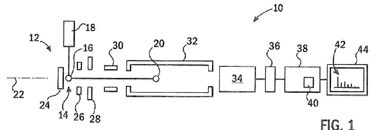
[0044]Referring now to FIG. 1, an example mass spectrometer 10 suitable for use with the present invention may include an ion generator 12, for example, providing an introduction zone 14 into which matrix treated molecules 16 may be introduced and targeted by a laser 18 to provide a source of ions 20. The ions 20 may be large molecules such as proteins, peptides, oligonucleotides and the like, that may be difficult to detect by conventional techniques.
[0045]The ions 20 may be accelerated along a travel axis 22 by means of various accelerating plates, for example, a repeller plate 24, positioned on a rear side of the introduction zone 14 and an attractor plate 26 positioned on the front side of the introduction zone 14 (in the direction of desired ion travel) with the attractor plate 26 having a relatively lower electrical potential than the repeller plate 24 (for positive ions). An accelerator plate 28 behind the attractor plate 26 may further accelerate the ions 20 to a desired spe...
PUM
 Abstract
Description
Claims
Application Information
 - R&D Engineer
- R&D Manager
- IP Professional
- Industry Leading Data Capabilities
- Powerful AI technology
- Patent DNA Extraction
Browse by: Latest US Patents, China's latest patents, Technical Efficacy Thesaurus, Application Domain, Technology Topic, Popular Technical Reports.
© 2024 PatSnap. All rights reserved.Legal|Privacy policy|Modern Slavery Act Transparency Statement|Sitemap|About US| Contact US: help@patsnap.com