System And Method For Multi-Source X-Ray-Based Imaging

a multi-source, x-ray-based technology, applied in the field of systems and methods for imaging a subject, can solve the problems of complex system b>10/b>, heavy and sophisticated control hardware and electronics, and high manufacturing and maintenance costs, and add to the complexity and cost of these systems

Active Publication Date: 2016-02-25
WISCONSIN ALUMNI RES FOUND
View PDF3 Cites 5 Cited by
  • Summary
  • Abstract
  • Description
  • Claims
  • Application Information

AI Technical Summary

Benefits of technology

[0013]The present invention overcomes the aforementioned drawbacks by providing a system for computed tomography (CT) imaging implementing a modular design including multiple x-ray sources. More particularly, a multi-source x-ray tube is provided that is able to deliver high current from an arbitrary number of focal spots. The system may include a fixed number of electron beams that are electromagnetically swept over a cooled target. Utilizing a modular design, the x-ray tubes can be arranged in a variety of configurations to suit a particular application. Using this design, unique scanning and radiation control techniques can be implemented, including rotation-free CT imaging, multi-energy imaging, and virtual filtering. Furthermore, active cooling of components is available in any given module.

Problems solved by technology

As illustrated in the picture of FIG. 1B, this system 10 is complex and requires heavy and sophisticated control hardware and electronics.
Accordingly, CT systems are generally complex and carry very-high manufacturing and maintenance costs.
All of these and other control and programming capabilities add to the complexity and costs to these systems.
As such, the trend toward greater and greater complexity of CT systems continues and, in particular, is prevalent when one considers the components and systems coupled to the gantry 12.
Thus, the complexity of the gantry systems 12 doubles, which further increases the underlying costs of the system and the maintenance requirements.

Method used


Image

  • System And Method For Multi-Source X-Ray-Based Imaging
  • System And Method For Multi-Source X-Ray-Based Imaging
  • System And Method For Multi-Source X-Ray-Based Imaging

Examples


Embodiment Construction

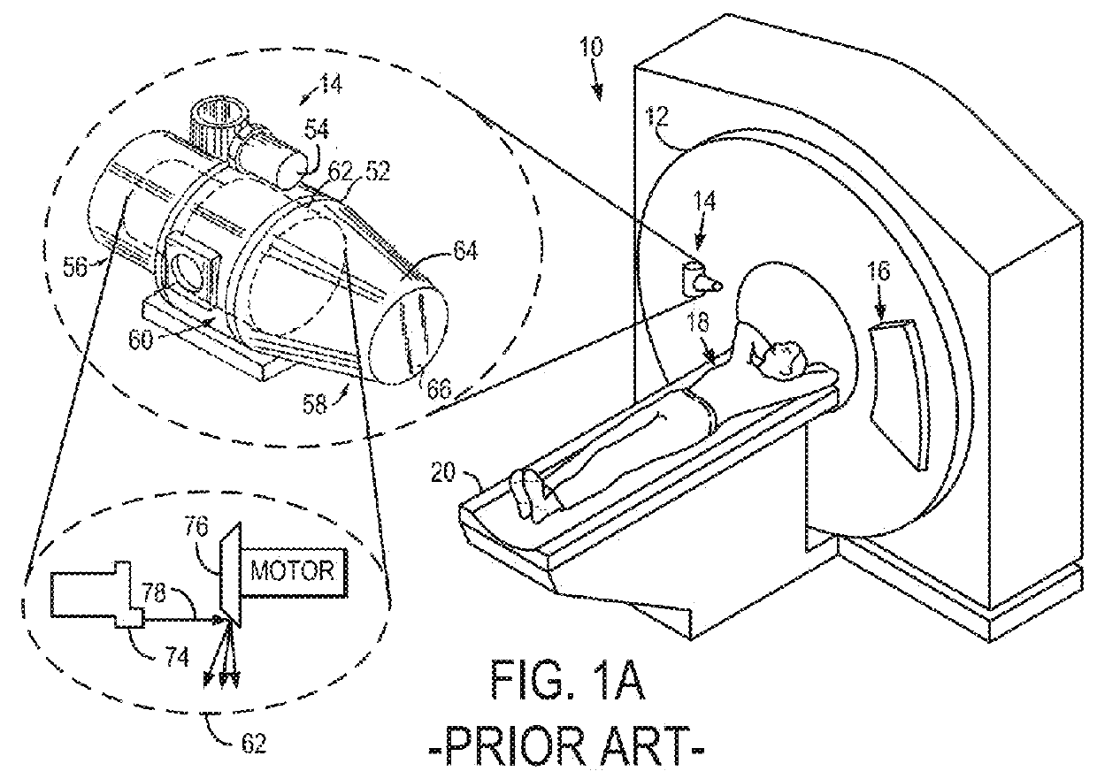
[0026]Referring to FIG. 1A, the x-ray tube 62 used in computed tomography (CT) systems 10 has, essentially, remained unchanged over the past 80 years. The modern x-ray tube 62 has a single cathode 74 that emits electrons towards a rotating anode 76. In CT scanning, two rotations are involved. First a rotation of the target anode 76 inside the tube and a rotation of the whole x-ray tube 62 on the gantry 12 about the patient 18. The target anode 76 must rotate extremely fast in order to avoid melting the x-ray tube 62 because there is only a single electron beam 78 constantly directed toward the same spot on the anode 76. This requirement for a rotating target anode 76 makes the standard x-ray tube 62 quite complex and difficult to build. The reliance on a single electron beam 78 means that the entire x-ray tube 62 must be rotated around the patient 18 with the gantry 12 for a complete CT scan. This introduces costs associated with a rotating gantry 12, and mechanical challenges with ...


PUM


Abstract

An imaging module includes a plurality of cathodes and respective gates, each cathode configured to generate a separate beam of electrons directed across a vacuum chamber and each gate matched to at least one respective cathode to enable and disable each separate beam of electrons from being directed across the vacuum chamber. A target anode is fixed within the vacuum chamber and arranged to receive the separate beam of electrons from each of the plurality of cathodes and, therefrom, generate a beam of x-rays. A deflection system is arranged between the plurality of cathodes and the target anode to generate a variable magnetic field to control a path followed by each of the separate beams of electrons to the target anode.

Description

GOVERNMENT RIGHTS[0001]N / A.BACKGROUND[0002]The present disclosure relates generally to systems and methods for imaging a subject and, in particular, to systems and methods for performing imaging processes using x-rays delivered from multiple sources.[0003]X-ray-based imaging, including so-called “x-ray imaging” and computed tomography (CT) imaging, are some of the most common diagnostic imaging modality used in modern medicine, enabling rapid, non-invasive image acquisition at high resolution. As shown in the example diagram of FIG. 1A, conventional CT systems 10 generally include a gantry 12 fitted with a X-ray tube 14 or at most, two X-ray tubes for systems currently in clinical use and opposing detector assembly 16, which, together, rotate about a subject 18 arranged on a patient bed 20 to acquire multiple projections for reconstructing an image. That is, the X-ray tube 14 and detector assembly 16 arranged opposite the X-ray tube 14 are affixed to the gantry 12 and rotate togethe...

Claims


Application Information

Patent Timeline
Patent Type & Authority Applications(United States)
IPC IPC(8): H01J35/04A61B6/00A61B6/03H01J35/06H01J35/12H01J35/14
CPCH01J35/045H01J35/12A61B6/4007A61B6/035H01J2235/068H01J35/14H01J2235/1204H01J2235/127H01J35/06A61B6/032A61B6/06A61B6/4014A61B6/4021A61B6/405A61B6/4488H01J35/30H01J35/066H01J35/13H01J35/153A61B6/40A61B6/482A61N5/1077H01J35/00H01J2235/1262
Inventor MACKIE, THOMAS R.WALKER, BRANDON J.SEATON, JONATHON R.
Owner WISCONSIN ALUMNI RES FOUND
Why Eureka
Try Eureka